photographs
refurbishment
description
refurbishment
Emulator
Museum Exhibits
| Radar Head photographs |
Console 61 refurbishment |
Console 64 description |
Console 64 refurbishment |
Radar Emulator |
Photographs of Museum Exhibits |
This article appeared in the December 2000 edition of the CHIDE magazine "Transmission Lines"
and is reproduced here with Keith's permission and help.
No one who has had anything to do with radar can fail to be aware of that far-reaching invention in wartime - the achievement of high power microwaves from the cavity magnetron by Randall and Boot at Birmingham University in February 1940. That single achievement, backed up by vigorous development engineering in industry - notably GEC at Wembley - quickly permitted vast improvements in airborne radars and resulted also in new generations of ground radars. Within about a year, radars working on wavelengths of around 10cm had become a reality. The availability of useful power at such a short wavelength enabled airborne radars to produce narrower beams of radiation than had hitherto been possible at 1.5m, and thereby overcame the previous range limitations caused by ground clutter. Ground-based radars, too, could now generate more accurate patterns of radiation to improve their measurements of target bearings and heights.
All this is well known, but it is not always appreciated that the magnetron has been with us ever since and has provided good service in many forms since WW2, not only for more modern radars but for other applications as well, including the ubiquitous microwave oven and as the power source for linear accelerators used in radiation therapy.
The first magnetrons of 1940 worked at about 10cm wavelength and by the middle of the war detailed improvements had resulted in ground-based centimetric radars producing peak pulse powers around 500kW at a pulse length of almost 2 microseconds and a repetition rate of 500 pulses per second - a mean power rating close on 500 watts. This meant that the relatively compact 10cm radar transmitters were actually more powerful than those of the giant CH stations working on wavelengths a hundred times longer. The output of CH stations varied somewhat but a typical East Coast transmitter might produce 700kW peak power during a 20 microsecond pulse at a repetition rate of 25 pulse per second. That is a mean power of only 350 watts and actually less than the much smaller microwave sets!
 |
 |
In wartime, cavity magnetrons were made at even shorter wavelengths for equipments such as 3cm H2S. Vast numbers of excellent magnetrons were produced in the USA following the ground-breaking demonstrations of early British samples during the famous Tizard Technical Mission of 1940.
After the war major valve manufacturers on both sides of the Atlantic continued with magnetron development so that soon they became available in a wide range of powers and wavelengths from a few millimetres to about 25cm. A popular 3cm application was in low power marine navigational radars (such radars need only low power since they detect large targets such as other ships and land masses, unlike defence radars which have to detect tiny targets at long ranges).
Probably the most outstanding post-war development, however, was a completely new configuration known as the "long anode" magnetron. Until then it had been usual to place the copper anode of the valve, into which the resonant cavities were machined, within the poles of a permanent magnet. But the need for a strong and uniform magnetic field had restricted the depth of the cavities and the permissible cathode area, thus limiting the power capability of the valve (see Fig 1).
In the new design, pioneered after the war by the same Dr Harry Boot who had worked with Sir John Randall in 1940, the cathode and the anode with its cavities were much longer and the magnetic field was obtained by inserting the whole into an electromagnet. Extensive development of the 'Boot Magnetron' by the English Electric Valve Company included valves producing 5MW peak power at 10cm and highly reliable long-life production versions giving 2.5MW at 5 microseconds pulse width and 300 pulses per second: a mean rf power of 3.75kW. This was a significantly useful increase over previous valves in the 10cm band and the Boot magnetron became a favourite workhorse for many defence radars from the late 1950s onwards when increasing importance was attached to high transmitter power for combating the threats of noise jamming in any future conflict.
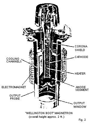
Towards the end of the 1950s, a 25 cm long anode valve (dubbed the "Wellington Boot" on account of its greater size) was developed and used in the Type 84 long-range defence radar designed by Marconi Radar for the RAE. See Fig 2 which shows the form of construction and how it was contained within a water-cooled electromagnet. The power output was 5MW peak, 12.5kW mean, at a pulse length of 10 microseconds and pulse rate of 250 per second.
Since a magnetron has no control electrode, such as the grid in a triode valve, it can only be pulsed by turning its HT supply on and off - a function performed by a suitable pulse modulator. Electrons emitted from the hot cathode and attracted to the anode are constrained into circular paths by the action of the magnetic field and interact with the resonant cavities to sustain oscillation for the duration of the applied pulse. Like all self-oscillators connected to aerial systems, the magnetron is sensitive to rf loading and may be pulled slightly in frequency according to the nature of the impedance into which it looks. The phase of any mismatch seen by the magnetron depends on the electrical length of the output line (waveguide) which in turn depends on the frequency. This interdependence can result, especially with long waveguide runs, in a situation where the magnetron persists in hopping about in frequency and was a serious problem with some early installations. From the 1950s onwards, however, it became possible to shield the magnetron from the effect of mismatches by fitting ferrite isolators between it and the rest of the waveguide system.
Magnetrons can also be pushed slightly in frequency by changes in the amplitude and shape of the applied pulse. Pulse modulator designs have improved enormously and nowadays the rate-of-rise of voltage is carefully controlled and particular attention is paid to automatic adjustment of the amplitude should the magnetron misbehave by sparking internally (even the best may cough sometimes).
Used with isolators and clever modulators, today's magnetrons run smoothly and provide reliable service for many radar applications including some Air Traffic Control installations at airports. The magnetron is a dogged thermionic survivor in this largely solid-state century.
In essence a magnetron is a simple valve consisting of two electrodes - a cathode and a rather special sort of anode with cavities in it - and a transverse magnetic field. What could be simpler than making a diode? The answer is that almost anything could be simpler when that diode happens to be a magnetron! I have known experienced valve engineers at their wit's end trying to solve problems of magnetron performance or inexplicable failures. Production magnetrons have to pass many tests including power output, frequency, spectral purity and missing pulse rate. Once a production line has managed to produce a good yield those concerned are often highly reluctant to impose any change in design or procedure, however slight, in case it "mucks things up". To a bystander like me, who has never made magnetrons but only used them, it smacks almost of magic and witchcraft. As an American engineer once remarked with feeling "...some of the stimuli to which the magnetron responds are quite subtle".
But, for all that, the magnetron has done us proud and we must be grateful to those who worked so patiently, for years, towards its perfection.
 |
s.jpg) |
|
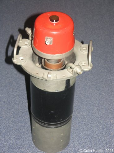
A magnetron from a Type 84 Radar, the right hand image showing the long anode structures. |
||
If you have any comments, complaints, suggestions, requests etc, please drop me a line via my Genuki email page.
Page last updated 30th January 2018 by Colin Hinson.