 |
 |
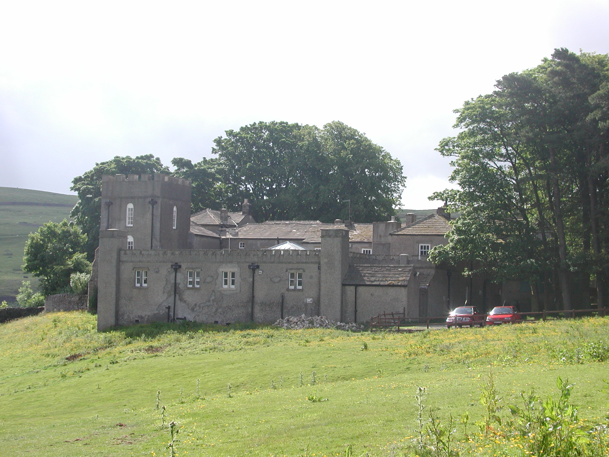
Grinton Lodge |
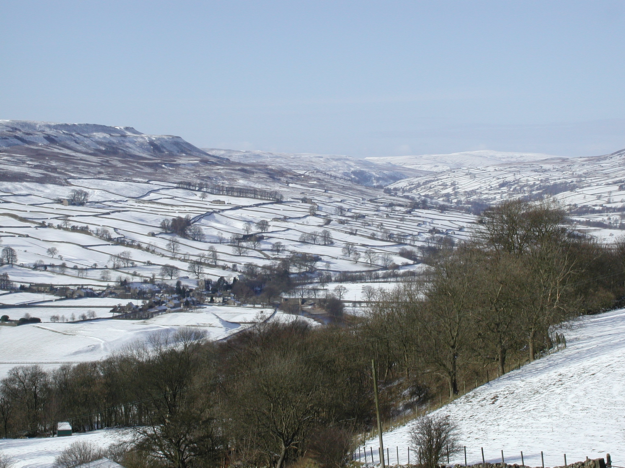
Swaledale in the snow |
I was brought up at Grinton Lodge in Swaledale, now in North Yorkshire, (it was then in the North Riding) where my parents were the wardens at the YHA Youth Hostel.
In general, the options for a career were Gamekeeper, Sheep Farmer, Dairy Farmer, Road man (remember them?), or to work at Catterick Garrison. A friend of mine introduced me to electronics first in the form of field telephones (guess where he worked), and then in the form of a radio. I decided that electronics was for me and on attempting to find out what I needed to do to get taught electronics at school (Richmond Grammar school), the answer from the headmaster was "There's no future in electronics, you'd be better off doing chemistry or history" (he had a degree in history). I found an advert for apprentices in the R.A.F. and answered it, took the exams and passed and was asked when I wanted to join - May or September. Things were not good at school, I was in the sixth form, six science. If you were in six science then you had to do Latin (the six arts did woodwork in the same period!). The only reason they could come up with was that in a chemists shop, then drawers were labelled in Latin, but the straw that broke the camel's back for me was when the headmaster decided that everyone in the sixth form should hand in an essay of 500 words, once a fortnight, about a history subject. I told the headmaster I was leaving his school (not very politely) and joined the R.A.F. in May 1958 at the age of 16. I have no regrets about this, and talking to people at a re-union this year, I wasn't the only one who left due to the headmaster.
At R.A.F. Locking as an apprentice in the first year, we were taught history and geography in addition to Radio theory etc., besides R.A.F. things such as drill. After the first year we had to choose which trade we would like to do: Air Radio, Air Radar, Ground Wireless or Ground Radar. You needed high marks to get to the Radar trades, and I had those so I chose Ground Radar which I never regretted. We were taught theory, practical and fault finding, along with workshop stuff such as soldering, filing, drilling and also taught about internal combustion engines by Diesel Dan. (I can't remember his proper name).
I left R.A.F. Locking with a really good grounding in electronics and particularly radar and with 2 years accelerated promotion. There's a summary of my career in the R.A.F. on my Radar page at https://blunham.com/Radar. I should add that the radars we were taught were very high power early warning search radars - multi megawatts output power.
Before explaining about radars, first some explanation of some of the terminologies and acronyms:
The radars I worked on were all pulsed microwave radars, and used a pulse length of about 10 microseconds. The radar transmitter sends out a high power microwave pulse and at the same time a trace (scan) is started on a CRT. When the pulse hits (for instance) a metallic object such as an aircraft, some of the pulse energy is reflected and some causes rf (radio frequency) currents in the skin of the aircraft which re-radiates. A receiver on the radar detects this energy and displays it on the trace on a CRT. The distance of this pulse display on the CRT from the start of the trace is proportional to the distance of the aircraft from the transmitter.
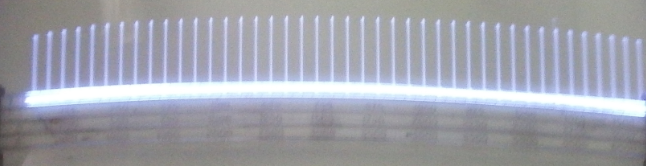
A 'radar mile' is about 12.23 microseconds (the time taken for the pulse to travel one radar data mile (2000yds) and back again). So, if internally generated pulses are displayed on the CRT every 61.8 microseconds (i.e. every 5 miles) then the distance of the aircraft from the radar can be calculated easily.
 |
 |
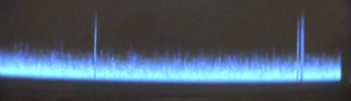
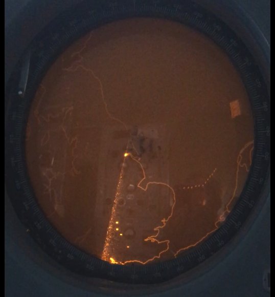
A-scan with targets
|
A-scan with 5 mile calibration
markers |
The rate at which pulses are sent out is known as the Pulse Recurence Frequency (prf). There is an optimum prf for any given radar because you shouldn't transmit another pulse until all the returns are received from the previous pulse output. For instance, most of the radars I worked on had a prf of 250. This meant that there were 4,000 microseconds between pulses which gives a maximum range of just over 320 radar miles. An airfield radar with a prf of 1000 would use a maximum range of around 80miles - the output power required for this can easily be calculated. If you put out too much power, then you will still be receiving returns from the previous pulse(s) and clearly you don't want pulses being detected at the receiver from the previous transmission(s). However this does sometimes happen under anomolous propagation conditions, for instance I have seen the Spanish coast appear in the English channel - very confusing!
The frequency of the radar will determine the minimum beam width for that radar. The radars in the early part of WWII used metric frequencies in general, CHL used around 200Mc/s (now MHz) for instance. The lower the frequency, the wider the beam width and so the display of the aircraft on a PPI screen would be wider. The wider the display the harder it is to distinguish how many aircraft there are when they are flying close together.
Towards the end of the war, magnetrons came into use and this gave micro-wave capability as seen in the Type 13 height finder and Type 14 search radars. These radars had a beam width of about a degree, which meant that separation of aircraft on the display was a lot better. Search radars have rotating aerials and use a Plan Position Indicator (PPI) display, the maximum speed of rotation is governed by the beamwidth - the smaller the beamwidth, the slower you must rotate. If you rotate too quickly the returned pulse from the target will be outside the beam width of the aerial and so you will miss it. All the radars I worked on had a prf of 250 and rotated at 4 rpm.
The early radars used 'A-scan' displays as shown in the photos above. These were horizontal displays for the trace with vertical deflection for any returns and receiver noise.
Later radars used Plan Position Indicator (PPI) displays where the trace started in the centre of the CRT and moved to the edge of the screen. The trace was rotated so that you could see where the aircraft were with respect to the radar. On these displays you could superimpose range rings and video maps. There are videos of PPI displays on my Radar page.
 |
A Plan Position Indicator (PPI) display |
At the start of WWII, the radar in use was Chain Home. This transmitted 50 pulses per second synchronised to the mains, and was a 'broadside' transmitter, which means that it illuminated a large part of the sky in one general direction (known as the 'line of shoot'). In order to get an accurate bearing of any targets, a receiver with a much smaller beamwidth was used, the receiver aerial being rotatable. The main problem with Chain Home was that it couldn't receive from behind the aerial, therefore once aircraft had gone past it, they couldn't be detected.
Later in the war came Chain Home Low. This was used to detect medium and low flying aircraft. It used an AMES type 2 radar. It transmitted at around 200Mc/s, at a prf of around 400 and a peak power output of 100kW at 25kV HT. The later radars Type 13 and 14 could work at a prf of 250 or 500 - later in their lives they ran at 250 prf all the time.
During the war, there were lots of Chain Home stations. After the war the number was reduced due to the better radars. In the 1950s, the 'Rotor' station was introduced; ROTOR had been instituted to provide a new radar defence chain in view of the rapidly deteriorating relations with the USSR in the 'Cold War' era (these used Type 7 (metric) and Type 13, 14 and an American FPS3 (all three being centimetric radars) ).
 |
 |
 |
Radar Type 7 |
Type 13 |
Type 14 |
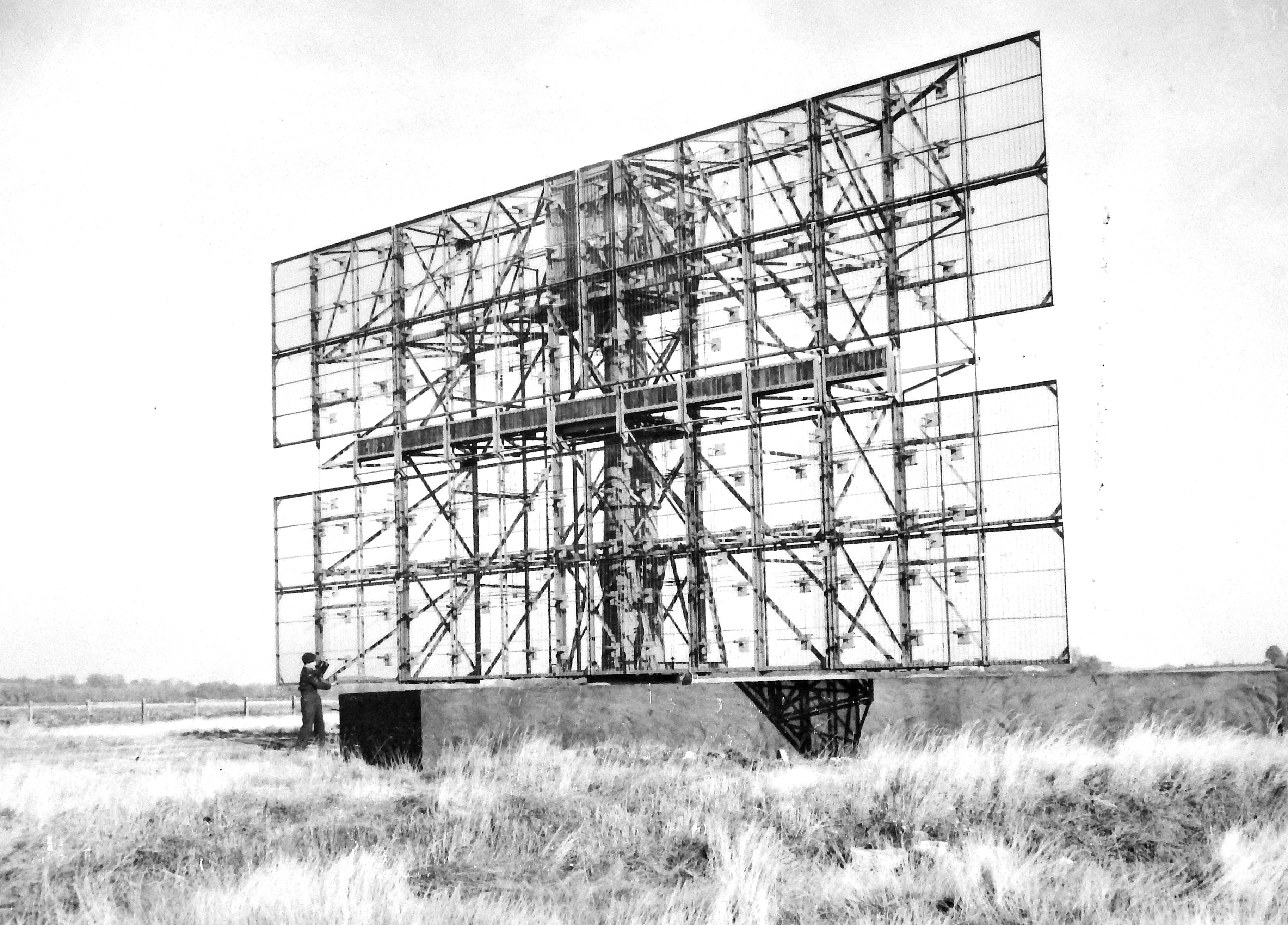
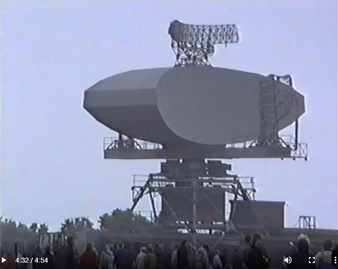
In the late 1950s, the FPS3 was replaced by the Decca Type 80 radar, which I was taught at Locking. The Type 80 was installed at a lot of stations - usually 40 to 50 miles apart on the coast. However the Type 80 was a game changer - it was far better that had been thought, and so a lot of the stations were removed, it being pointless having radars with a range of over 240 miles being 40 miles apart. The Type 80 radar used a 75 foot cosec squared linear array with an end fed slotted waveguide. The slots started off near horizontal and gradually increased in angle until they were vertical at the far end. This gave an even power distribution across the array.
 |
Decca Radar Type 80 |
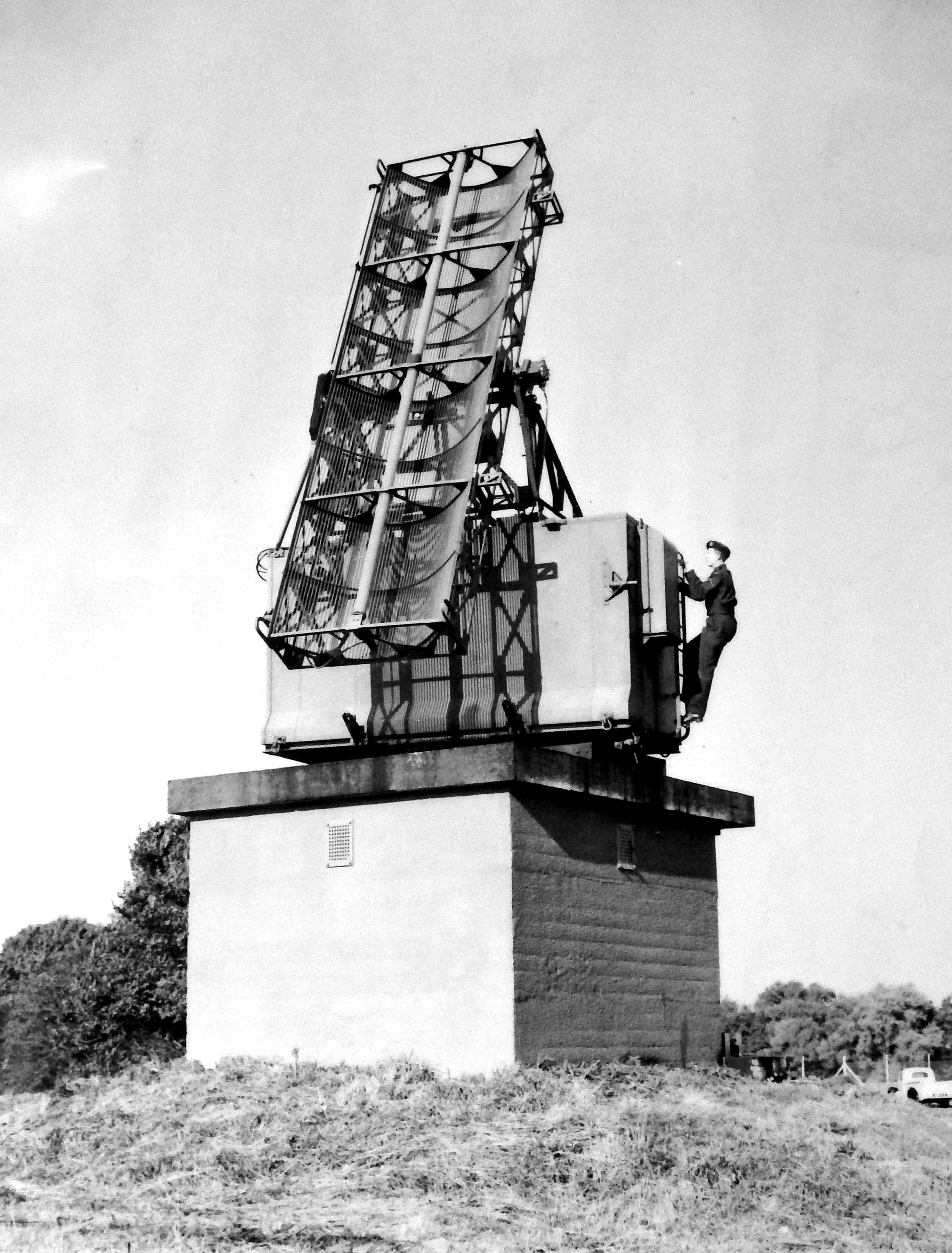
Height finder radars, such as the Type 13, had a nodding aerial with a small beamwidth in the horizontal and vertical directions. To determine the height of an aircraft, the PPI operator would cause the height finder to rotate so that it was pointing at the aircraft, and then the height finder operator would calculate the height from a series of lines drawn on the height finder display. The PPI operator had electronic feedback from the height finder so that he/she knew the direction in which it was pointing. The early consoles had a mechanical cursor which rotated through a tell-back system of selsyns (see below).The later consoles had a marker on the display which also rotated through a tell-back system. Height finding can also be done with radars with multiple beams such as the later Type 85 and the modern 3D radars..
A selsyn is a rotating transformer with mains in and 3 phases out. As the rotor rotates so the 3 phase outputs change dependent on the position of the rotor, and by connecting another identical selsyn to the 3 phases and the same mains, the second selsyn is made to rotate in synchronism with the first. On a radar site, the first selsyn is connected by a 1 to 30 gear box to the radar head (aerial) and so the selsyn in the console can drive the deflection coils round the neck of the tube through a 30:1 gear box and stay in synch. with the radar head.
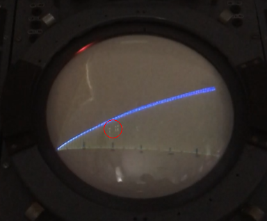 |
Height Finder display showing 3 aircraft (circled in red) |
At the end of the war PPI consoles, such as the Console 60, had moving coils to rotate the display ie. the coils rotate around the neck of the CRT. The later Consoles from the early 1950s were 'Fixed Coil' and used X and Y sawteeth waveforms to rotate the display. There were several advantages to this, for instance in the inter-trace time (the time between the end of one scan and the start of the next) you could display markers such as the height finder position.
Later, early 1960s, systems allowed positioning of the height finders with a joystick, which also had a marker, see below for descriptions of these Consoles.
My first posting after my apprenticeship was to R.A.F. Patrington, 20 miles east of Hull. Patrington was a Master Radar Station and had a Type 7, Type 80, Type 13's and FPS6's (American Height finders) and a Type 54 (CHEL). The T13, 14 and 54 all used the same transmitter and receiver. The Type 54 sat on top of a 220ft tower and used a dish aerial to produce a pencil beam and could see ships out to about 80 miles.
After 3 years at Patrington, I was detached to R.A.F. Staxton Wold to work on Linesman Radars, starting off with the Type 84 radar. I spent 10 years at Staxton apart from 2 years at Mount Olympus in Cyprus working on Type 84 and HF200 radars.
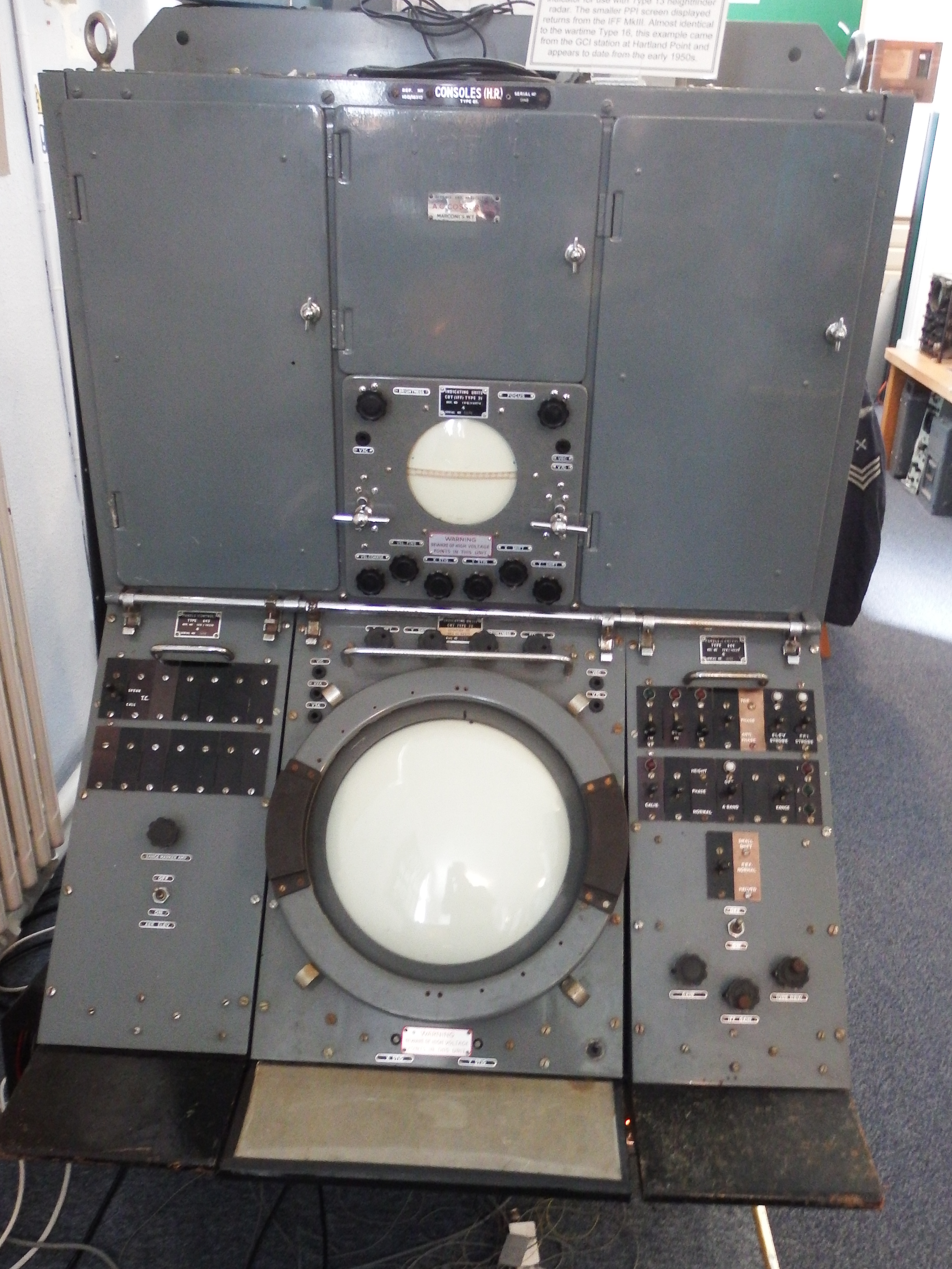
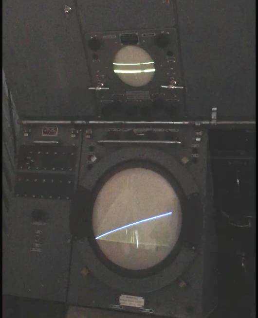
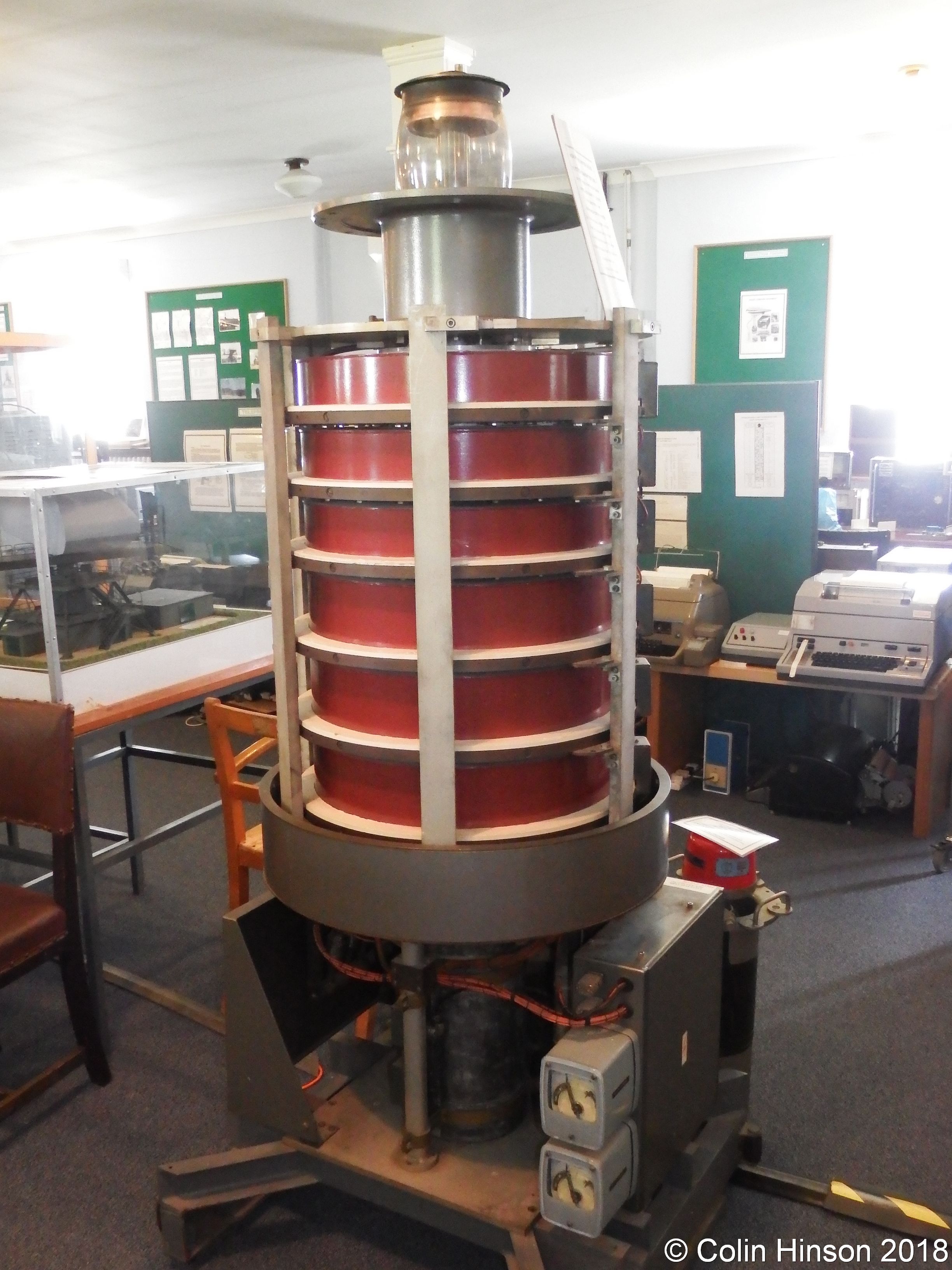
At the Henlow Signals Museum we have 3 radar consoles, all usually working. The consoles are working with the same inputs as they would have had when in use on a radar station, with the one exception that the X and Y for the Console 64 is at 12volts instead of the original 50 volts. The displays are generated by Arduino processors with software written by Paul Edwards. There are two of these, one for the Console 60 and one for the Console 61/64 combination. Paul designed the software (with system inputs and the rare "C" input from me), along with the design of the supporting hardware. Most of the circuitry is on a wire wrap board in each of the units which were built by me. Wire wrap is a lot quicker than soldering the connections and a lot easier to modify.
 |
Console 60 |
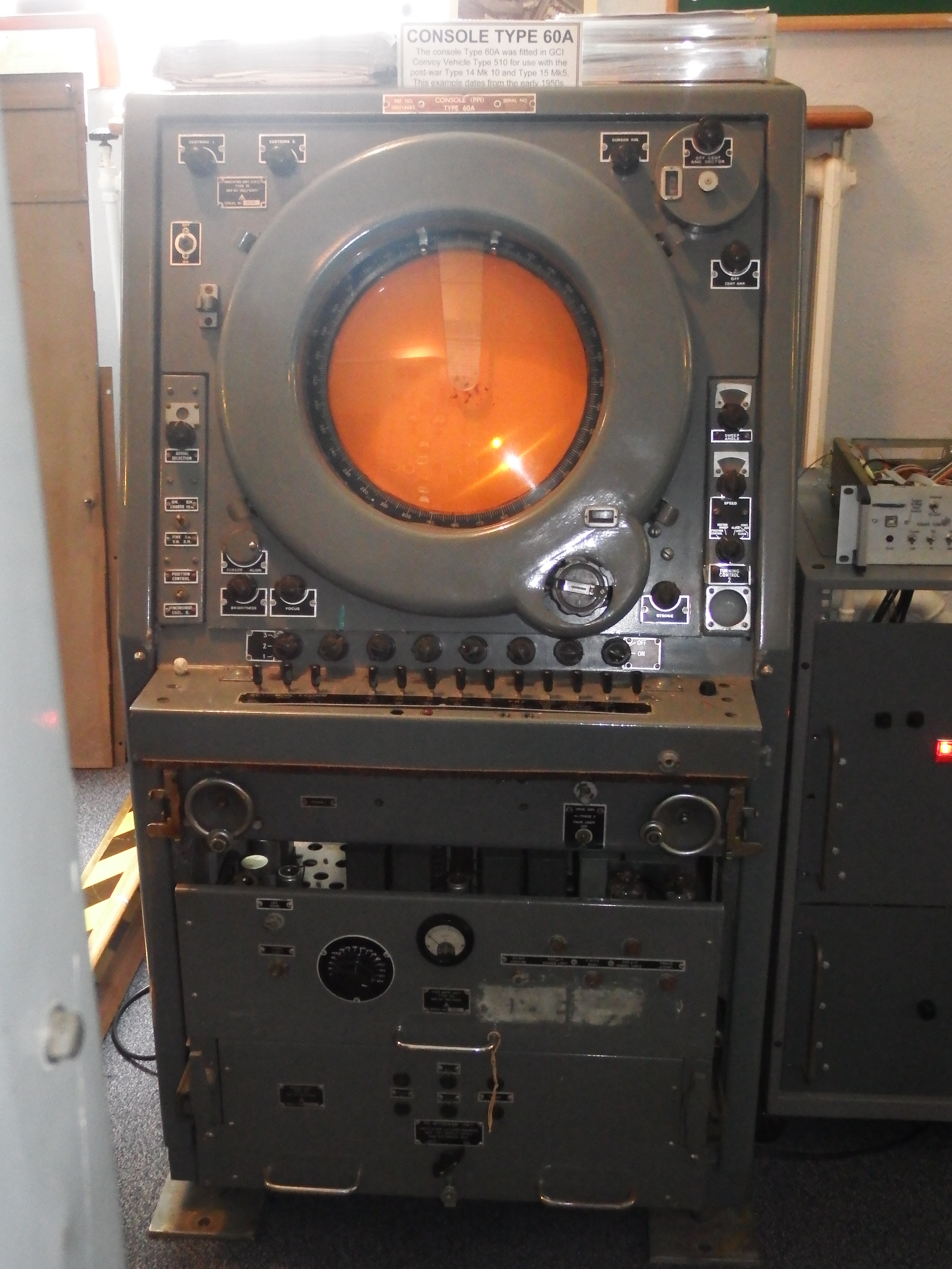
Console 60.
An early moving coil PPI console with a long persistance display was designed mainly for use in mobile systems and usually carried in an RVT 510 vehicle. It generally displayed the output from the Type 14 or the type 15. I met this console at Mount Olympus in Cyprus in 1963/4 when it was being used for the Type 84 display in an RVT 510 - where they dragged this up from I don't know! I was never taught about this console, fortunately it never went wrong while I was on shift. The input signals for each of the radars are: Radar video, IFF, range rings, video map and a common trigger. The console can select one of 3 radar input from the control desk and also has switching so that it can work with 2 radars back to back thereby giving twice the coverage over 180 degrees. At the bottom of the unit are the power supply and the timebase unit (which needs only a trigger at the start of the trace). The unit has a hardware cursor which is normally swung out of sight.
The moving coils for the display are driven by a selsyn system. An auto-align system is used to get the two selsyns in the north position at the same time.
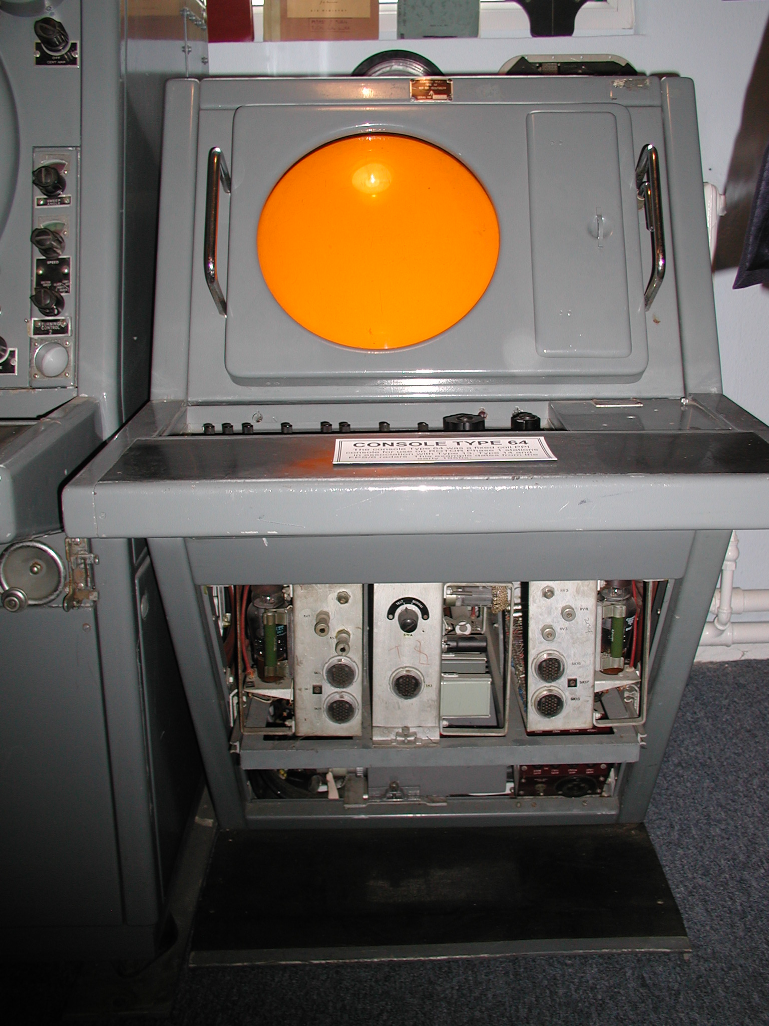 |
The Console 64 with the bottom cover removed to show the 2 deflection amplifiers and the voltage stabliser. |
Console 64.
I was taught about this excellent reliable console! As previously mentioned, it has a fixed coil display and has no power supplies in it (these being remote in the 'Radar Office'). There were lots of different control desks that were used in various situations. At Locking, the desks were of the Fighter Controller variety which contolled the height finder in conjunction with the Console 61 operator, and it is one of these that we have at the museum (now with an added joystick). The display is a very long persistance (about 4 minutes maximum) amber CRT. As previously mentioned the X/Y display deflection waveforms are 12volts instead of 50volts. The main reason for this is that 50volts op-amps tend to go bang for no apparent reason and are expensive. Fortunately the deflection amplifiers have valve operational amplifiers on their inputs and so changing the gain of these was simply a case of changing the value of the feed back or input resistors. The console is capable of selecting up to 12 different radar heads (we only have 3). For each head the display can consist of: radar video, IFF, range rings, video map, inter-trace markers (height finder and joystick), range strobe (for the Console 61). Each of these has an amplitude control. The display can be off-centred and the range changed (80, 120, 240 and 320 miles). The range change always takes place about the centre of the display. There is also an anti-clutter switch which can blank out up to the first 30 miles or so to remove ground clutter.
On our console at the museum I have fitted a joystick. This is used to control the height finder (or to write your name on the screen). To control the height finder you put the joystick dot on the aircraft you want the height of and then request the height finder. On the later Fixed Coil (phase 1A), this would put you in a height finder queue (there could be up to 12 fighter controllers and only 5 height finders at the most). When you were allocated the height finder, the strobe marker would appear on the screen (instant in our case) and would then rotate to the location of the joystick dot. When the height finder operator got the height, it would appear on one of three tumbler displays at the rear of the control desk.
At Patrington in the phase 1A fixed coil, the height finder displays were also on the Console 64. The original FPS6 height range indicator was awful to maintain so this was a really pleasant surprise. The Type 13 height finder console had been the then obsolete Console 61. There were 5 of these consoles, one for each of the height finders. The nodding display had a 'tadpole' inter-trace marker which the height finder operator could move with a joystick which could only move in the Y direction (up and down), the range of the marker being controlled by the fighter controller requesting the height. The operator would put the marker in the middle of the target (usually about 3/4 of an inch in height) and press the 'send' key so that the fighter controller would get the height on his control desk. The height finder operator could be requested to give two heights in succession when interceptions were taking place - one for the target aircraft and one for the interceptor under his control. A computer consisting of uniselectors and relays would work out the heights from the joystick voltages and also work out the difference in height. All three numbers were sent to the fighter controller by means of the 3 digit tumbler indicators at the rear of the console control desk.
 |
 |
 |
| The Console 61, doors open | The Console 61, the doors closed | The Console 61 displays. |
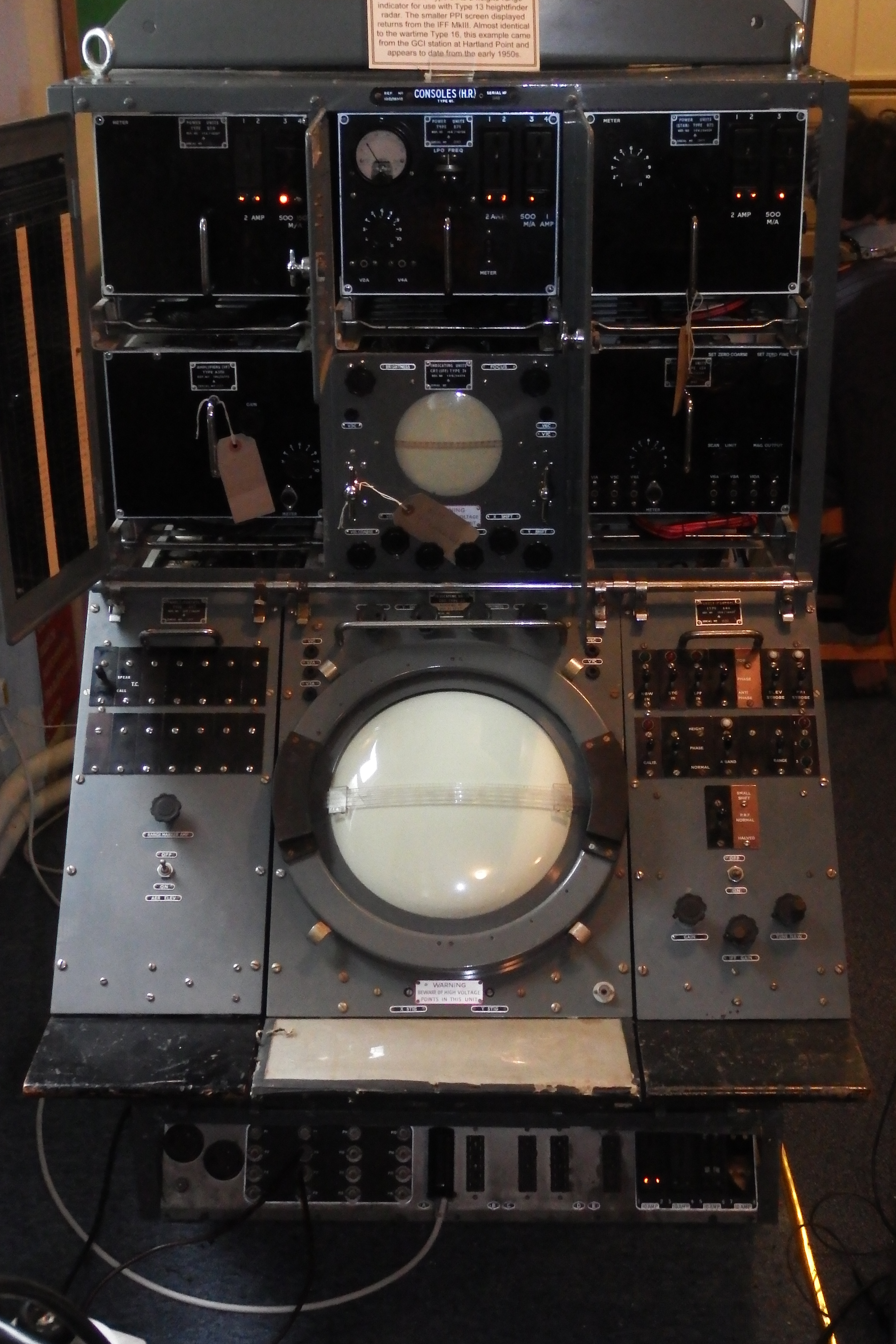
Console 61 (the earliest).
This Console was a development of the DU5 display used with CHL. It could be used as either an A-scan display (horizontal) or as a nodding height finder display. The CRT is a 12 inch blue phosphor device with 5kV for the high voltage. It contains a receiver whose input is 45Mc/s i.e. the Intermediate Frequency of the Radar receivers. Each of these was attached to one height finder.
The receiver can be set to narrow bandwidth and short time constant for anti-jamming purposes. At the museum we use this mainly for the height finder display. The console also has a second smaller display which has two scans on it, one for IFF and one for and upside down A-scan PPI video. The IFF was the Mark III version which used broad pulses and contained very little coding.
 |
 |
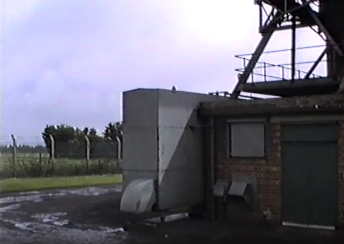 |
The Type 84 at Staxton Wold |
The hornstack |
The external air blower |
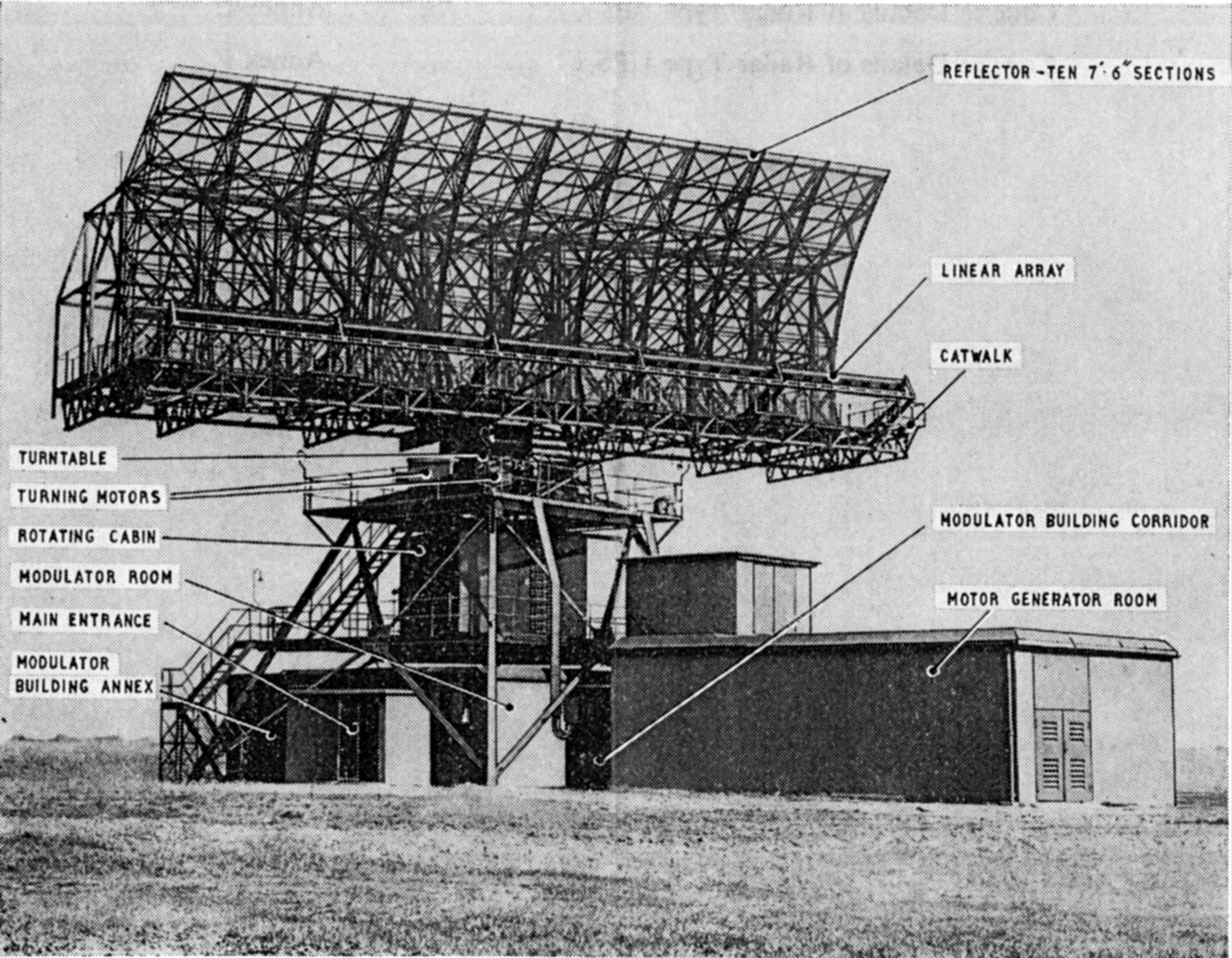
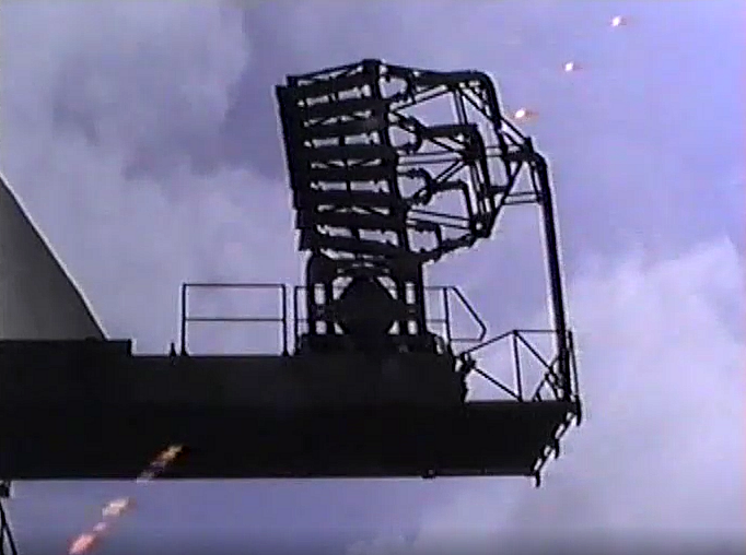
The Type 84 radar used a gantry and turning gear very similar to the Type 80, however the aerial was totally different. It had two solid reflectors back to back although only one was ever used, with a massive waveguide hornstack 'firing' into the reflector. The hornstack could be set to circular or horizontal polarisation. The circular polarisation was amazing in rain, but reduced the range somewhat. Unlike the Type 80 which had a lot of equipment in the rotating cabin, the Type 84 only had the rotating joint and the tell-back equipment such as the Selsyn (aka Tacho).
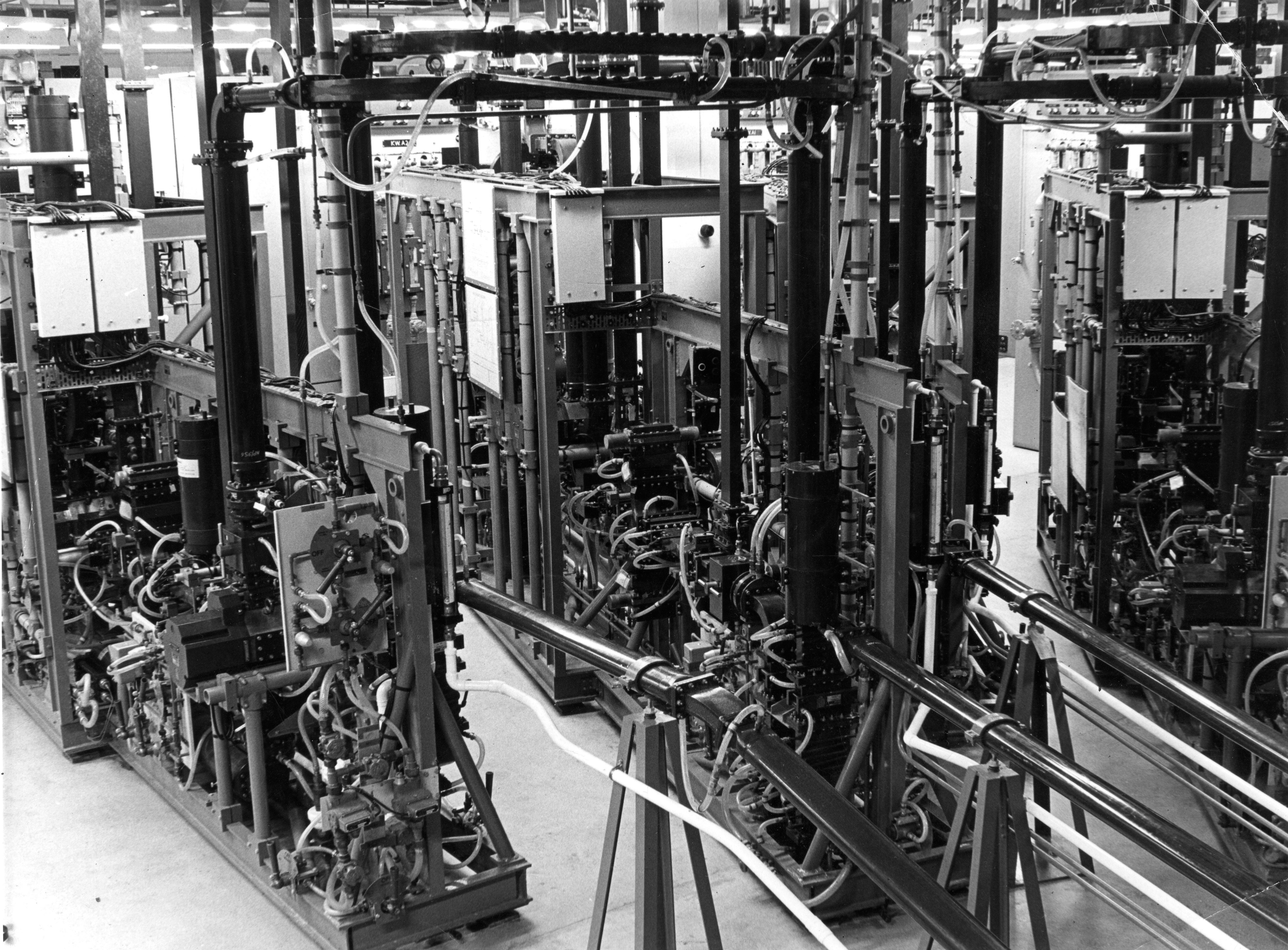
The transmitter and receivers were on the ground floor along with the DC generators for the 4 turning gear motors. The transmitter was a large water cooled magnetron giving around 4 megawatts peak power with 10kV HT. The heater voltage to the magnetron reduced as the HT was increased as the cathode was kept hot by the returning electrons. At the left hand side of the transmitter equipment was the HT variac which stood about 4feet high and 3 feet across with a massive contactor on top of it. At the right hand side were the water and air pumps. The whole lot was kept cool by a big external fan system. The waveguide was kept pressurised by a system of two compressors and freezers in an annexe. The freezers froze all the water out of the air before it was sent to the waveguide which was kept pressurised to stop water getting in, every half hour or so, the compressors and freezers would change over to defrosting. There were (as I remember) 3 receivers, one linear, one logarithmic and one anti-jamming. The outputs from these were sent to the signal processing in the main building on the site.
The display for the Type 84 technical people was a suite of 3 Console 64's. Using these it was possible to set up such things as the MTI. The MTI was used to be able to see, or not see, moving targets and used multiple controls and a mercury delay line to achieve this. To set this up on (for instance) a stormy day with lots of clouds, you would pick a cloud system and put a rectangle over it. You could then adjust controls to set up the cloud's wind speed, velocity and direction. When you got this right, the cloud would disappear and as if by magic, any aircraft within the cloud would be visible - all done by valves! I seem to remember that you could have up to 3 different rectangles at any one time. There were lots of other controls here too - such as the circular polarisation.
There were also anti-jamming features available, in particular the anti-jamming receiver which was particularly good against Carcinotrons - these transmitted very wide bandwith white noise.
 |
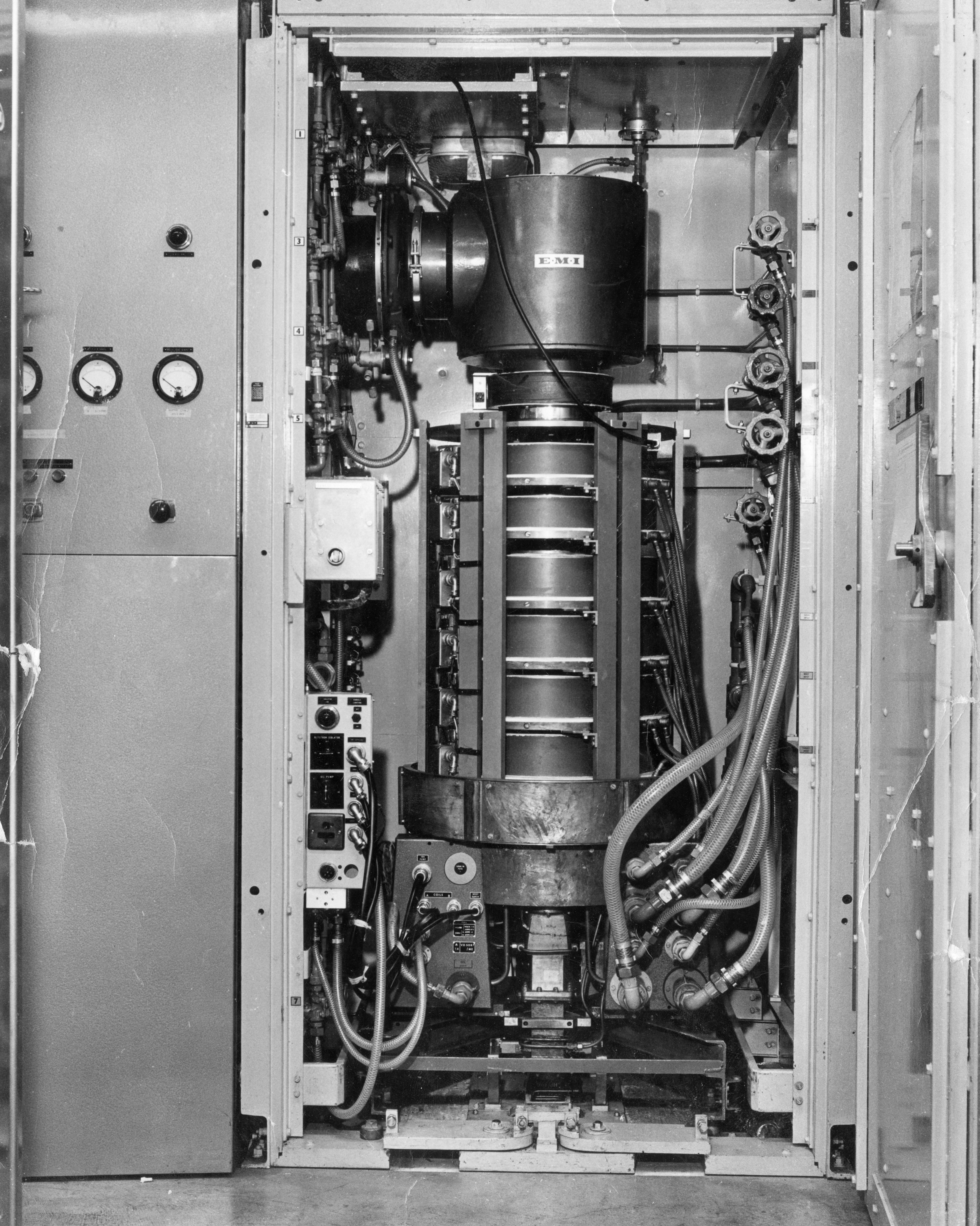
The Type 84 magnetron |
 |
 |
 |
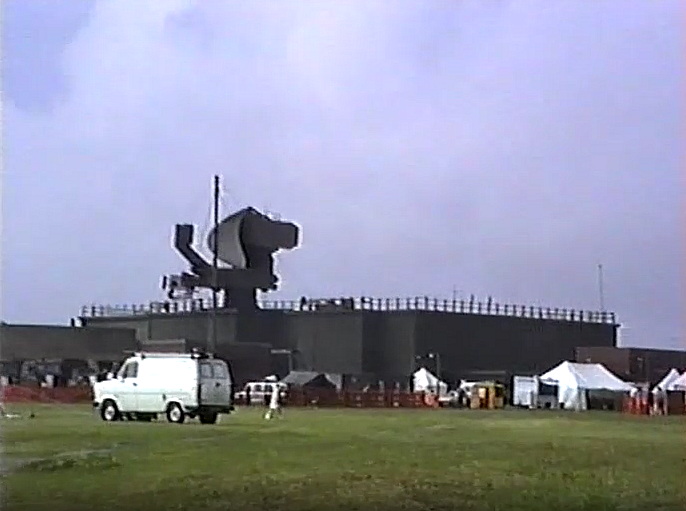
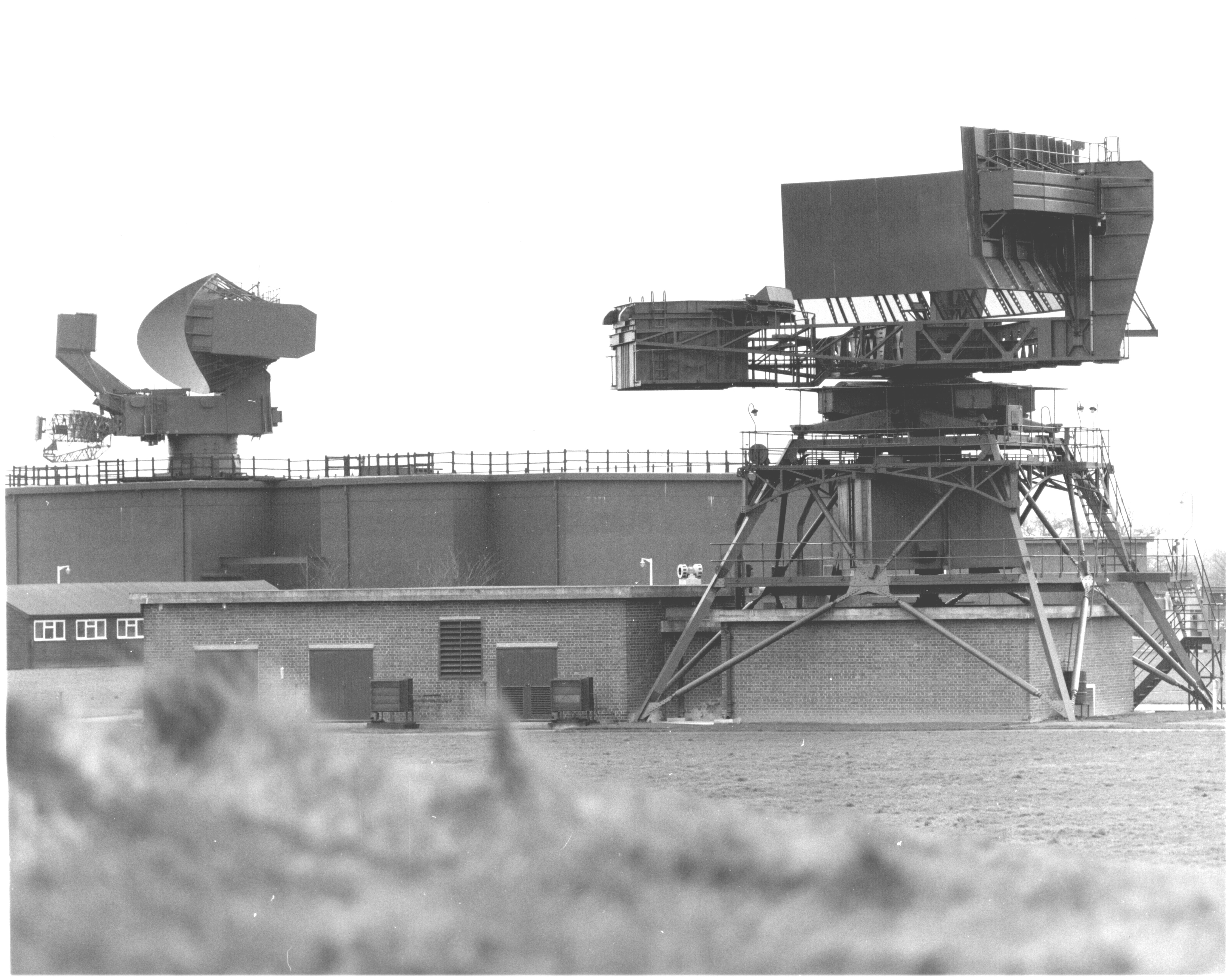
The Type 85 at Staxton Wold |
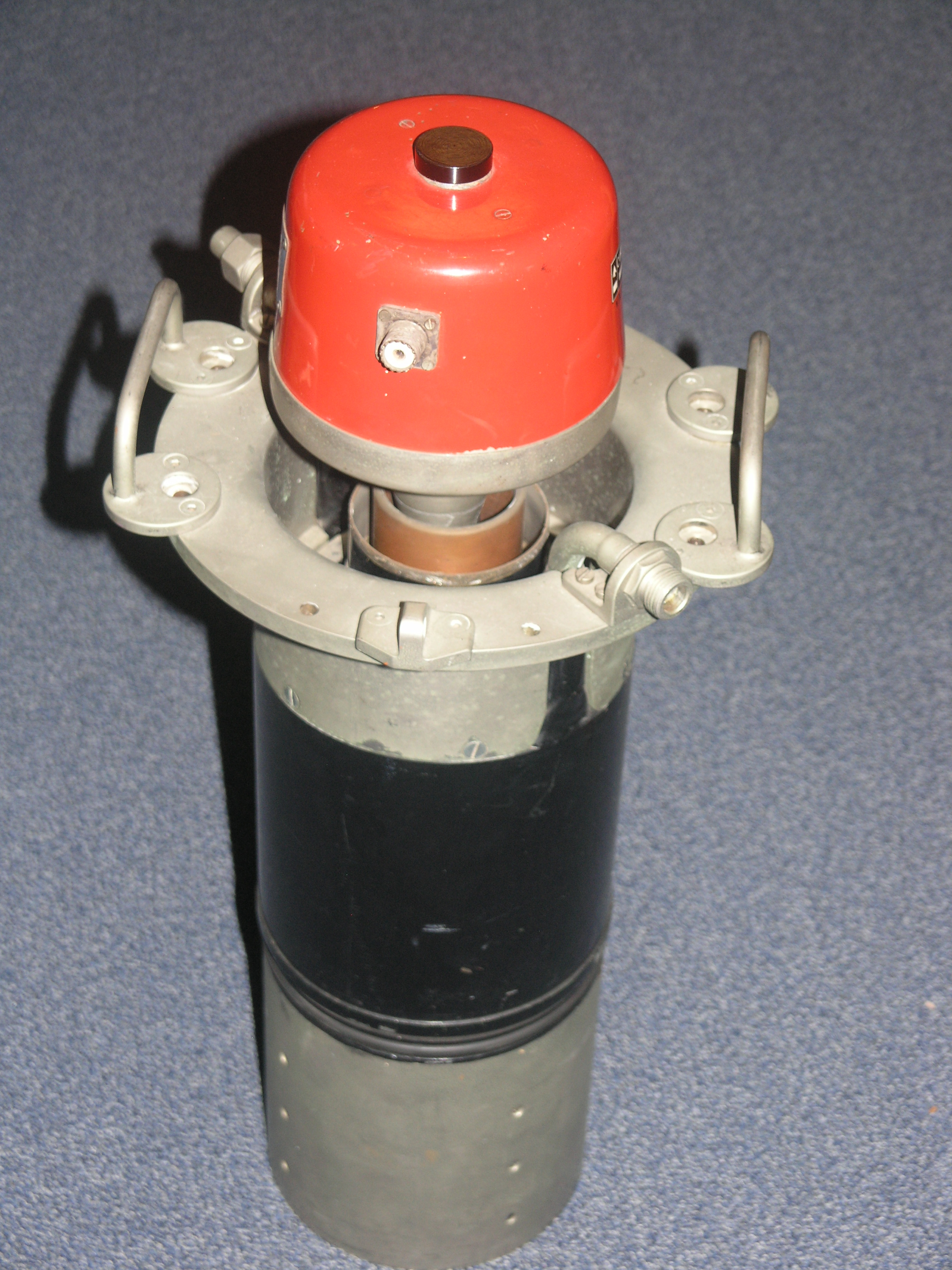
A Klystron in situ (about 6ft high) |
A Klystron at Henlow museum |
The Type 85 radar was a massive beast. It used up to 12 (normally 2) transmitters, each of up to 8 megawatts. It used klystrons as the transmitter amplifiers and so was frequency agile by simply changing the frequency of the inputs. It worked on 4 of the sub bands of the S band (A, B, D & E - the Type 80 used the C band). Each transmitter had numerous receivers - in such as linear, log and anti-jamming. Besides having anti-jamming receivers (similar to the Type 84), the Type 85 used its frequency agility to avoid the jamming - just before it was about to transmit it checked the receiver for jamming on that frequency and, if it found it, it shifted to a different frequency. The problem with this was that only the radar knew it was being jammed - this was eventually rectified.
The aerial sat on top of the main building on the site (known as the R12), and the hornstack set at the front of the reflector which was very similar to the Type 84 reflector.
The waveguides had to be seen to be believed - there's a photo of part of them on my Radar page. Each of the waveguides went through a switching system and then went through a pressure vessel and then to the hornstack. The pressure vessel was the height of the building (two floors) and something like 8 feet across - it contained the rotating joints. The transmitters took up the whole of the ground floor and the receivers and other equipment about a third of the top floor.
 |
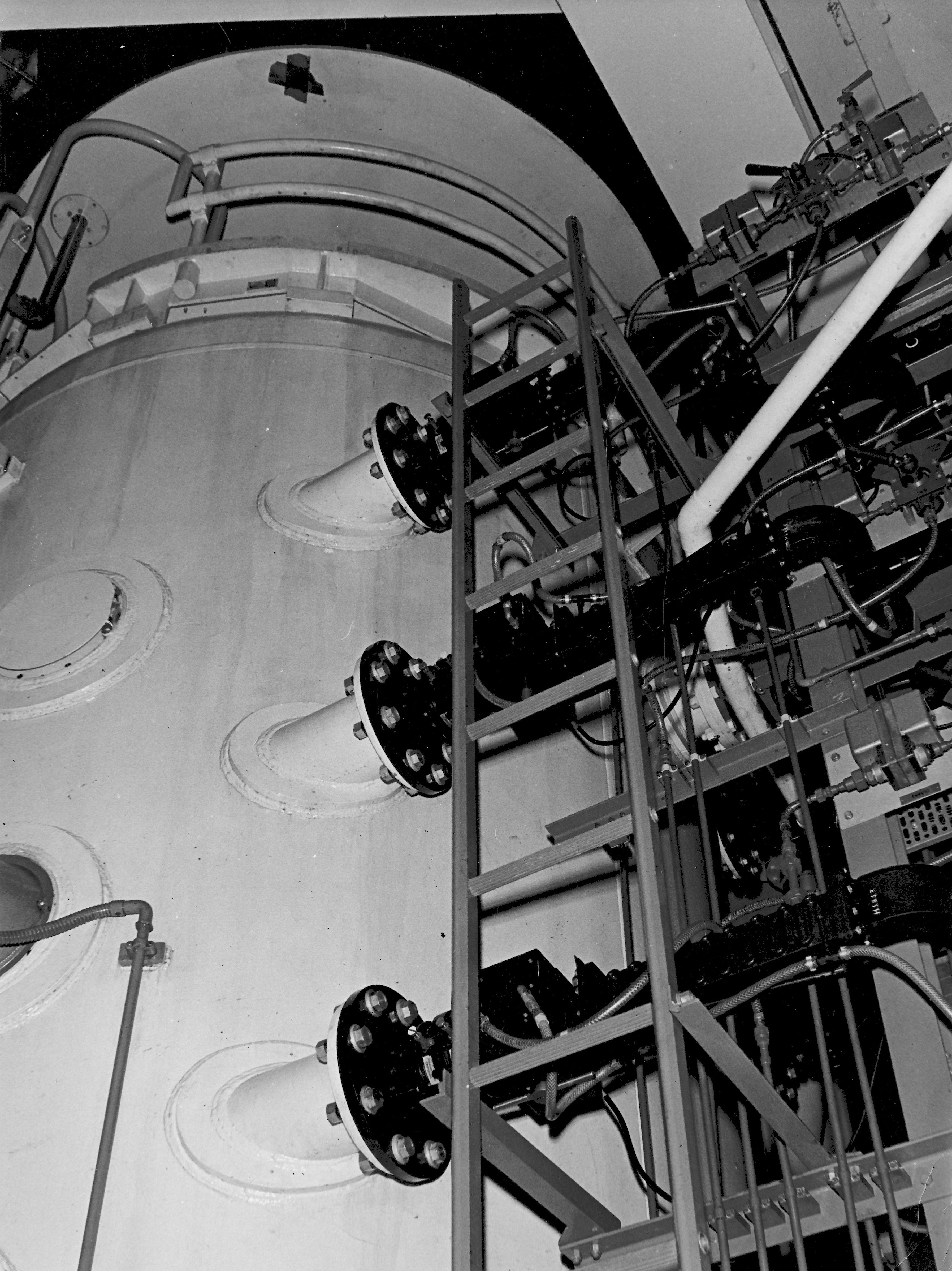 |
Type 85, 3 of the waveguide switches (out of 12) |
3 of the inputs to the pressure vessel |
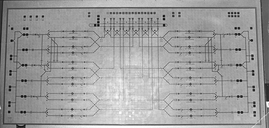 |
The Type 85 mimic diagram. Each of the square plaques was 1 inch (2.54cm) across. It was the main feature in the R12 control room. |
The Type 85 mimic had to be seen to be believed. Shown above, it was light green in colour and the appropriate lamps would be lit when the T85 was in use and showed which transmitter and which horns etc. were being used. Starting at the left are the frequency generators which feed all 6 of the band A and D amplifiers and transmitters, the B and E frequency generators and transmitters being at the right. From the amplifier and transmitter blocks are shown all the waveguide switching possible, the relevant run of lamps being lit for each configuration at the time. Right at the top are shown the horns, and below those is shown the pressure vessel. We were told that the mimic was a variation of Westinghouse railway signalling mimics. Under normal circumstances, only two transmitters would be in use (the top ones on the mimic) and in that configuration, they each tranmitted into 6 of the horns using power splitting in the switches.
There are lots more photographs and a few videos about radar on my Radar page.
In 1968, the NATO defence policy was changed to one of 'flexible response'. In the UK an entirely different air defence radar system was needed, with grater emphasis placed on hardening of the control elements, an enhanced flexibility in the deployment of radars to circumvent pre-targeting. Thus IUKADGE (Improved UK Air Defence Ground Environment) came into being during the 1980's, to replace LINESMAN; the radar sites were once again sited around the UK coast, and digitally linked in to the Command Centre.
 |
The Radar Type 85 and the High Speed Aerial |
Principles.
Jamming signals were to be detected at each end of an extended baseline, of the order of a hundred miles. One signal was transmitted to the other end of the baseline, and the two signals compared in a 'correlator'. A correlator is a device which will given an output when two identical signals (including white noise) are fed into a device in the same phase, that is, without any time difference between them. Therefore, after compensating for the delay in transmission, a variable delay can be introduced into one signal until correlation is achieved. The whole project carried the codename of WINKLE.
Implementation.
The final design involved signals detected at one end (Radar Type 85), and at the other end by a specially designed High Speed Aerial (HSA). This scanned a fixed angle in the horizontal plane once for each beam-width of the Radar Type 85; it was mounted on turning gear so that the fixed angle of scan could be moved for optimum coverage. Correlation when a target was at coincidence of the two achieved the objective, by giving its position with the same accuracy and data rate as the Radar Type 85. As you will appreciate, the positional data on jamming targets was three-dimensional because the Radar Type 85 had a 'stacked-beam' configuration, and PD was installed on each beam.
Footnote: [by John Brown]When I was involved in the Hughes Consortium bidding for NADGE(1964/5), I and my Marconi colleagues were pushing hard to get PD included in the Central Region and Flanks; however because the USA had nothing remotely to offer in competition, they blocked it at the NATO council. This was in spite of the UK government offering to make PD available to each competing consortium at the same bid price. Equally, I remember whenever any USAF visitors came to Staxton, they were envious of our PD - "we've got nothing like it - only wish we had!"
I left the R.A.F. in 1974 before the advent of phased array radars, and so very little about them as I went on to designing teletext decoders for Texas Instruments. There's a link to this part of my career at the bottom of my Radar page.
Colin Hinson
Acknowledgements:
John Brown, a former Staxton Wold Commanding Officer who contributed some information about Linesman, IUKADGE and Passive Detection.
Rosemary Jackson (a physics teacher) for proof reading and trying to persuade me to change various parts, in some cases succeeding.