Introduction
This paper is intended to review the possibilities regarding the design of modulators of approximately 50 Mw peak output at space to mark ratios up to 1000/1. There may be a use for such modulators for high power ground radar equipment and for particle accelerators for atomic energy work.
Taking a tentative output requirement as 120 Kv. 400 amps. and assuming that a sufficiently good pulse transformer of up to 1/4 ratio could be designed the effective modulator output would lie somewhere between 30 Kv. 1600 amps. and 120 Kv. 400 amps. These figures give some idea of the magnitude of the problem.
The first part of the paper reviews various types of modulator valve that have been used in the past and considers them from the point of view of this requirement.
The second part deals more fully with the preferred type of valve and gives details of the particular circuit that must be used with it.
PART I REVIEW OF POSSIBLE VALVE TYPES
1. Hard Valves
1.1 Oxide Coated Cathodes
The most efficient cathode from the point of view of emission current for a given heater power is the oxide coated type. Unfortunately, it is also the most difficult to outgas thoroughly and the most easily damaged by positive ion
bombardment. These two features make it unsatisfactory for use in high voltage valves.
There is a further disadvantage in the tendency for the cathode coating to evaporate and be deposited on other electrodes, from which uncontrolled emission may take place if they become too hot. Although gold or platinum-plated grid wires have been used to inhibit grid mission, the design of large valves is made more difficult by the necessity for extremely good cooling.
Valves so far developed have had peak working currents of about 0.2 amps/watt of heater power. The maximum output power per valve has been about 250 KW. at about 15 Kv. There seems little possibility of this being greatly extended.
1.2 Thoriated Tungsten Cathodes
Although a less efficient emitter than the oxide coated cathode, the thoriated tungsten type is less liable to damage from bombardment of positive ions, particularly when carbonised; the carbonisation process also materially reduces the rate of evaporation of thorium from the surface.
Owing to the higher working temperature, it can be degassed more effectively than the oxide coated type, and there is therefore no difficulty in operating it at higher voltages.
Practically no long term experience with such valves as modulators has so far been obtained. It is probable that a peak working current of about 0.05 amps/watt of heating power is obtainable. Such valves as exist have a maximum output of about 1.5 Mw. at a maximum voltage of 40 - 50 Kv. The required output could therefore be obtained by paralleling some 30 - 40 of these valves - an unpleasant prospect - or by designing a very much larger valve.
1.3 Tungsten Cathodes
Tungsten cathodes have not so far been used for modulator valves; they would be even less efficient emitters but have few real limitations.
1.4 Modulator Design
It is probable that a hard valve modulator suitable for any power could be made given sufficient time.
It is certain that for high powers it would be cumbersome and inefficient compared with other types of modulator; efficiency will be an important consideration at high mean powers.
The hard valve modulator, however, has advantages that cannot be obtained by other circuits. These may be summed up as precision and flexibility; it is possible that operational requirements might enforce the use of a hard valve modulator at some time.
2. Soft Valves
2.1 Mercury Thyratron
It is well known that the presence of gas in a valve enables a larger current to flow, other things being equal, since the gas becomes ionised by collision with electrons emitted from the cathode. The positive ions thus formed neutralise the negative space charge round the cathode so that the saturation emission is readily drawn. A gas filled valve is therefore a possible means of obtaining higher powers. Gas valves, however, always introduce circuit complications since, once operating, current can only be stopped by removing anode voltage and a period for deionisation must then elapse.
The earliest type to be used was the mercury vapour thyratron; this normally has liquid mercury in the bulb so that the pressure inside is the vapour pressure of mercury at the working temperature; the behaviour of the valve is accordingly temperature sensitive.
An oxide coated cathode is generally used in order to obtain the maximum emission. The space charge is reduced to such an extent that the voltage drop across the valve is only about 15 volts and under these conditions the ions have insufficient velocity to damage the cathode. The current flowing is substantially all electron current owing to the relatively slow movement of the ions. A further result of the space charge neutralisation is that heat-shielded cathodes may be used, giving further economies; also re-entrant cathode shapes which would be quite impracticable in a vacuum valve became possible.
The working temperature limits are determined by the increase in voltage drop at low temperatures which arises because of insufficient ionisation to keep the space charge neutralised and results in damage to the cathode by bombardment - and by the decrease in internal breakdown voltage at high temperatures due to excessive ionisation. It is essential to limit the rate at which anode current is allowed to build-up, since, until the gas is completely ionised, current begins to flow under space-charge limited conditions. This may cause damage to the cathode through positive ion bombardment or local overheating of cathode surfaces nearest to other electrodes and which temporarily carry the full current.
Mercury thyratrons have not been used for powers above Mw. and have scarcely been used at all for some years owing to the disadvantages of a fairly close temperature control, poor shelf life, unreliable working life and the complicated associated circuit necessary to provide long deionisation time.
2.2 Other Thyratrons
The use of fillings other than mercury vapour has been customary for some time in small valves; generally, one of the inert gases has been used, but these are unsuitable for high power valves owing to the low breakdown voltage. Hydrogen has now virtually replaced mercury vapour for
modulator thyratrons. The main advantages are the relative insensitivity to variations in temperature and the greater nobility of the hydrogen ion which enables ionisation and deionisation to be effected much more rapidly. On the other hand the voltage drop is greater (80 - 100 volts).
The mechanism of operation is similar to that of the mercury vapour valve, except that positive ion current will be a larger proportion of the total owing to the small difference in mass between the ion and the electron.
Design and manufacture of hydrogen-filled valves is very tricky, and very close control of all manufacturing processes is necessary. Failure occurs from loss of cathode emission or from clean-up of hydrogen, the latter being more common. There is a tendency to include metallic hydrides as hydrogen reservoirs to prevent clean-up.
The highest power so far attempted in this country is 2½ Mw. In America a valve for 140 Mw. output is under development but there is no enthusiasm for such a valve here as yet.
2.3 Ignitron
In the thyratron, the electron emitting source is always present, and current is controlled by a third electrode; in the ignitron, the emitter is formed when necessary by the action of the third electrode and there is no other control over the current. The cathode consists of a pool of mercury. The type which has been used experimentally has a igniter of resistive material dipping into the mercury surface. When current is passed through the igniter, local heating of the mercury surface at the point of contact occurs and a cathode spot is developed which is at a sufficiently high temperature to give thermionic emission. Ionisation of the mercury vapour then occurs, and further emission is available by virtue of secondary electrons resulting from positive ion bombardment.
There is substantially no limit to the current available, except purely practical ones such as heating of the bulb and seals.
Some development work on a modulator ignitron was recently carried out, using a mercury pool switch with a dipping igniter fired by a short pulse of 5 - 6 KV. This was intended for use at a power level of 5 Mw. Work was discontinued as igniter lives in excess of a few hundred hours were not possible.
2.4 Grid Controlled Mercury Arc
The main weakness in the thyratron lies in the cathode which is easily damaged, in the ignitron it lies in the
igniter. To overcome these difficulties the grid-controlled mercury arc valve is a logical step. This has a mercury pool cathode but an emitting source is always available in the form of a cathode spot which is permanently maintained by an auxiliary discharge. The discharge to the main anode is controlled by a grid as in the thyratron.
The mechanism of current-flow through mercury arc tubes is somewhat obscure. It is not known how much of the current is electron current and how much is positive ion current. The voltage drop tends to be somewhat greater than in thyratrons, but this is presumably unimportant (except that the losses will be higher) since the mercury pool cathode will not suffer damage from bombardment. For the same reason, temperature control is likely to be much less critical and to be mainly concerned with preventing the bulb from overheating. Should the valve be cold on starting, the voltage drop will be high and the temperature will soon rise by virtue of the internal heating.
A valve of this type has been designed for use at an output of 5 Mw. and has been run experimentally at a peak output of 50 Mw. with the recurrence frequency reduced to give the same mean output. A new valve is proposed for operation at a level of 50 Mw.
It is necessary to use these valves in a special circuit so that they can de-ionise after conduction, This is described in Part II of this paper.
The circuit makes use of two similar valves 'which are mounted in the same envelope with a common cathode. In addition to this, there is the excitation anode previously mentioned and an igniter electrode which is used to form the cathode spot when the valve is first switched on.
2.5 Spark Gaps
It is probable that a rotary spark gap and a blown triggered gap (or several in series) could be made to operate at the required output. A rotary gap giving 214 Mw. output was designed some years ago.
The rotary gap has many disadvantages such as noise, jitter, inability to lock the modulator to any source and so on; and has been obsolete for some years.
The triggered gap would also be objectionably noisy and past experience has shown it to be somewhat troublesome oven at 5 Mw.
PART II CIRCUIT AND VALVE DEVELOPMENT FOR HIGH POWER,
1. D.C. Transformation Charging Circuit
The reason for giving. more detailed consideration to this particular type of circuit is that it enables the grid-controlled continuous-excitation mercury are modulator valve to be used, and hence is capable of being applied to the generation of very high power pulses. The existing 5 megawatt rated mercury arc switch was developed specifically for use in this circuit and the arrangement has proved to be very flexible in respect of peak power and duty cycle, the controlling factor being the moan power limitation of the valve itself (5 Kw. at present).
This modulator circuit falls into the general class of those using a charged pulse-forming network which is switched by the modulator valve into the load, the latter being arranged roughly to match the characteristic impedance of the network. It differs from the more familiar forms in the method of recharging the network and in the input supply which it requires. The conditions to be met by the recharging circuit are that:‑
(a) In a time less than the interval between pulses the network must be recharged to the full voltage, and
(b) The recharge cycle must not commence immediately on completion of the discharge, but a significant interval for deionisation of the valve must be provided.
1.1 Basic Circuit
The basic circuit is shown in Fig. 1(a). The pulse-forming network is represented for convenience as a line with distributed inductance and capacitance, but inmost practical cases it will be made up of a relatively small number of sections (say, eight) of lumped series inductance and shunt capacitance. If each of the 'm' sections has component values 'ℓ' and 'c', then the characteristic impedance
Zo = √ ℓ/c and the pulse duration is 2m √ ℓc
The circuit action can be studied in two separate parts, namely the discharge of the network into the load giving the output pulse, and the recharge of the network from the supply.
The discharge circuit comprises the network N, the load R and the main modulator switch S2 in series and is shown separated in Fig. 1(b). This is the conventional arrangement, where, for optimum discharge conditions, R should equal Zo; this results in a single pulse and maximum output power.
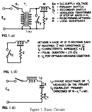
During the charging period, switch S2 is open, and the circuit action, on closing switch S1, becomes that of suddenly applying a D.C. voltage to the primary of a transformer (T1), the secondary of which is loaded by a capacitance. This arises because, at the relatively low charging rate, the network N behaves as a simple lumped capacitance. Under these circumstances, the transformer leakage inductance resonates with the network capacitance, and the circuit can be considered as of the simple equivalent form of Fig. 1(c).
It will be seen from Fig. 1(c) that the recharging system reduces effectively to one of resonant choke charging, but with the advantage of voltage step-up in the transformer T1. The inductance L2, in general, is supplied by the leakage of the modulation transformer, but in practice its value may be increased by external series inductance as required to give a suitable recharge time. We shall consider the effect of the primary inductance at a later stage, but to a first order this can be neglected. The apparent load impedance becomes the actual value R divided by the square of the transformer ratio and represents negligible series damping on the resonant L.C. circuit for most practical cases.
On closing switch S1, a voltage is built up sinusoidally on the condenser C2, the period for a complete half cycle from zero to maximum voltage being π√ L2C2 During this time, the current through the switch S1 rises from zero to its maximum and returns to zero again by the end of the half-cycle; provided that the switch can be made effectively open-circuit from this time onwards (say, by virtue of its unidirectional properties), the condenser will be left charged to a voltage equal to twice that of the D.C. supply (except for a relatively slow discharge through the winding inductance of the transformer). This means that the pulse-forming network will tend to remain at a voltage equal to twice the product of the D.C. supply voltage and the ratio of the transformer T1.
Once having charged the pulse-forming network and open-circuited the switch S1, then the discharge cycle can be initiated in the normal manner by closing switch S2, and the circuit remains in a quiescent state until S1 is again closed. The repetition rate is determined by the frequency of closing S1 and can be varied over wide limits. Switch S2 must be arranged to close at a time approximately equal to π√ L2C2 after the closing of S1. The effect of a small advancement or retardation of the time of closing of S2 relative to the instant of zero current in S1 is dependent upon the nature of the switches, and will be considered in more detail later. For the moment, it is sufficient to say that, from elementary considerations, one might expect that considerable retardation would be tolerable, but that advancement might lead to trouble in the primary circuit. At any rate, the exact time of firing of S2 should not be too critical.
Turning now to practical considerations, we see that the switch S2, which we shall assume to be a gas discharge valve of some type, in order that it may have adequate peak current carrying capacity, has favourable deionisation conditions. Having discharged the network completely in the pulse duration, there is no re-application of forward voltage across it for what can be an appreciable fraction of one repetition interval. The switch S1 also needs to be a valve of the gas discharge variety as it has to handle a high mean current at a low voltage (say 500 volts) and to have a small voltage drop to prevent excessive loss. With the circuit in the form shown, it will be apparent that, immediately upon the zero current state being reached, the valve S1 must begin to deionise and there must be no tendency to restrike before the next recharge cycle is due. However, once the network is discharged, the secondary of the transformer T1 is short-circuited and the voltage across the primary approaches zero, leaving the full forward D.C. voltage impressed across S1 and making satisfactory deionisation of this valve unlikely. This leads to loss of control in the circuit and some modification is necessary to overcome this difficulty.
1.2 Modified Circuit
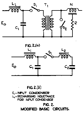
Consider now the circuit shown in Fig. 2(a), which is modified from that of Fig. 1(a) by the introduction of an input condenser C1 connected to the D.C. supply (Eo) through a large inductance L1. The simplified equivalent circuit, which applies during the period when switch S2 is open is shown in Fig. 2(b). In this, the inductance of the transformer winding and the load resistance are neglected.
The aim of the modification is to ease the operating conditions for the primary valve S1 by providing a period, it after the current has fallen to zero, during which the anode is negative with respect to the cathode. The condenser C1 has a capacitance which is made less than C2, so that, at the end of the network recharge period, condenser C1 is left negatively charged, the actual amount of the negative overswing being a function of the ratio C1:C2, and the recharging time now being determined from the inductance L2 and the two condensers C1 and C2 in series. The inductance L1 is arranged to give substantially linear (constant current) recharge of condenser C1 during the quiescent period following the network recharge and discharge cycles; this involves the use of a choke several times the inductance required for resonant recharge in the available time period.
With the arrangement as above, the waveforms of voltage across C2, voltage across C1 and current through S1, are as shown in Fig. 3.
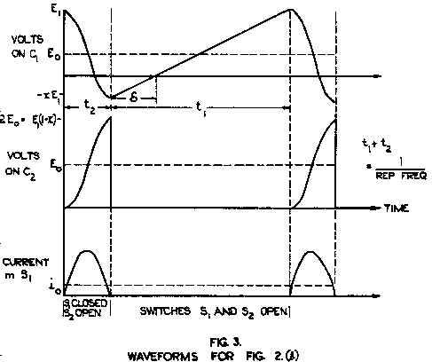
An analysis of the circuit shows that this modification does not affect the voltage to which the condenser C2, or in the practical case the pulse-forming network N, is charged, the latter being equal to twice the product of the D.C. supply voltage and the transformer turns ratio. This implies that the voltage of the pulse delivered to the matched load R on discharge remains equal to the product of the supply voltage and the transformer turns ratio. This relationship is independent of the value of the ratio C1:C2 and of the time interval t1 and t2, provided that the resistive loss in the circuit can be neglected add that there is a negligible voltage drop across the valve S1. The charging inductance L1 may be of such a value as to give resonant or substantially linear recharging of the input capacitance C1, the latter condition being used if variable pulse repetition frequency is required.
The time interval 'δ' during which there is no reapplication of forward voltage across the primary valve S1 is the feature which enables a normal gas discharge valve to be used in the circuit without danger of "firing through". From the geometry of the above waveform diagrams, it is evident that it can be increased, for a given pulse repetition frequency, either by increasing the time-interval t1 at the expense of t2 or by decreasing the ratio C1:C2 with a corresponding increase of overswing. In either case there are practical limits to what can be done in these directions, as decreasing the interval t2 results in a higher peak current in S1 for the same output power, and decreasing C1 (C2 being fixed by the output requirements) results in a higher forward voltage as well as higher reverse voltage on the condenser C1 and across the valve S1. However, this is not a serious matter as in most practical cases a satisfactory deionisation period can be provided. To give some idea of the order of magnitudes, the ratios C1:C2 . 0.5 and t1:t2 = 5, have been used successfully.
1.3 Practical Considerations
If we consider now the respects in which the actual transformer-coupled circuit differs from the simplified equivalent circuit as examined, perhaps the most significant omission is the effect of the finite value of winding
inductance (so far assumed to be infinitely large). The more
complete equivalent circuit for the network charging process is as shown in Fig. 4.
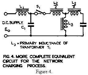
It will be seen that, during the network recharge period, a voltage is impressed across L3 which is the mean between the voltages across C1 and C2. From the geometry of these waveforms, already given, it will be seen that the voltage across inductance L3 approximates to a steady value equal to the D.C. supply voltage Eo, provided that there is no excessive overswing on the input condenser
C1. Hence there is a linear rate of rise of
current in the winding inductance L3 for the charging period t2, and the current. established at the time that that switch S1 opens is equal
to Eo/L3 • t2. During the
quiescent period (t1), the energy left in the inductance proceeds to share between L3 and C2 with a periodic time equal
to π√ L3C2. This period will, in general, be long compared
with the network recharge period (t2), but may be of the same
order as the quiescent period (t1). In the limit we have the
condition where all the energy appears on the network, in the form of reverse voltage, by the time of the commencement of the next network recharge cycle. Such a condition, leads to forward overvoltage on the network when the steady state is
reached. This in itself would not be important as it could be compensated by a reduction in the supply voltage Eo, but it does lead to a modulator output which is sensitive to pulse
repetition frequency. In view of the losses which are associated with the sharing process in practice, it is desirable to make the initial current in the inductance L3 as low as
possible in order to maintain a high overall efficiency. It
is important to note that, due to the repetitive nature of the process, and to the fact that the current in L3 builds up, in general, from a finite value and not from zero, the steady-start value of the maximum current will exceed the value
Eo/L3 • t2. The factor by which it exceeds this value is
dependent on the relationship between the quiescent period (t1)
and the natural oscillatory period π√ L3C2.
In most practical modulators of the same general type, reverse diode protection is provided to limit the network voltage in the event of appreciable load mismatch or intermittent load short-circuit. The diode with a limiting, series resistor is connected in shunt across the network and the simplified equivalent circuit which applies during the quiescent period when both switches are open is shown in. Fig.5.
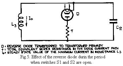
It is evident that in the energy-sharing process already mentioned, energy will be absorbed in the diode and resistance which represent parallel damping on the oscillatory circuit. It can be shown that a choice of 'r' equal to the critical damping resistance (½√ L3/C2 ) gives the least value of Io for a given winding inductance, consistent with small dependence of output on pulse repetition frequency. Under these conditions it is possible to calculate and plot the circuit loss as a function of the ratio t1 : √ L3/C2 for given values of the on-off ratio t2:t1. Although, as would be expected, the curves reveal the least loss for the highest value of L3 in every case, they further show that there is a region over which the loss does not increase seriously. This is particularly important from the transformer design point of view, as to increase considerably may be quite impractical on account of size and weight. For a value t2:t1 = 0.2, the loss is less than 1% of the output up to the value t1/√ L3/C2. Thereafter it begins to rise more rapidly. The lower the ratio t2:t1, the higher the values of t1 which can be used for the same percentage loss. Having fixed the values of t1 and t2 from other considerations, the above relationship enables the minimum winding inductance L3 to be determined.
In the case of the D.C. transformation charging circuit a time t1 is available for the reverse diode to fulfil its normal function of removing the network overswing, whereas in the conventional resonant and linear-charged modulator circuits the time constant of the network capacity with the diode circuit resistance must be a small fraction of the pulse repetition period. Taking a value 'r' = √ L3/C2 and using an inductance such that √ L3/C2 = tl, we have rC2 = t1/2. Thus the value of 'r' which is dictated by considerations of the current stored in the transformer winding inductance is quite satisfactory for over-voltage protection, the overswing being reduced to 1/e² (or 13.5%) of its original value in the time available.
1.4 Circuit Rearrangement
So far the two switches S1 and S2 have not been considered in detail. As these switches are to be gas discharge valves in practice it is convenient to rearrange the circuit in order to have the cathode of each at earth potential. Such rearrangement is shown in Fig. 6.
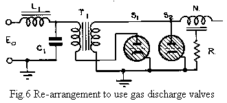
In Part I, it was shown that the grid-controlled mercury arc valve was singularly suitable as a modulator for very high power pulses. It therefore becomes an obvious choice for valve S2, which is the main modulator. A similar type of valve is also suited to operation as S1 in view of its high current carrying capacity and its low voltage drop. From this it is a logical step to consider having a composite mercury arc valve with a common mercury pool cathode, but two separate anodes and control grids. Such a valve has been developed for use in the D.C. Transformation Charging circuit and is described in more detail below.
2. Grid-Controlled Mercury Arc Valves
This composite valve is shown in Fig. 7. The excitation
takes the form of an auxiliary electrode to which is applied
a D.C. potential of the order of 50 volts. The initiation of the excitation arc is achieved by using ignitron action, the igniter being made of resistive material dipping into the mercury surface. Approximately 50 volts D.C. is first applied to the igniter and the exciter together, but once the excitation arc is established the voltage is removed from the igniter. In this way the igniter comes into play only on starting up for the first time, and hence wear is of little importance. A choke is used in series with the excitation anode so as to stabilise the arc, and the valve normally runs with an excitation current in the region of 3 amperes.
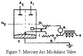
A1, A2 are the two main anodes. A2 is insulated for a hold-off voltage of 20 KV.
G1, G2 are the two control grids.
E is the auxiliary excitation anode.
I is the igniter, used for starting up.
C is the mercury pool cathode.
There are internal baffles between the two halves of the valve to prevent undesirable interaction.
Each control grid is normally biased to -500 volts and triggering may be achieved, in each case, by a 5 microsecond pulse of approximately 1000 volts amplitude developed across a 2000 ohms impedance. The circuit in which it is used demands that one grid shall be triggered a given time after the other on each cycle, and hence it is convenient to provide the two trigger pulses from a square wave generator, one pulse corresponding in time with the loading and the other with the trailing edge of the square wave. By making the square wave of adjustable space-mark-ratio, the trigger signals can be phased for optimum operation of the valve.
This valve has the following general rating:‑
Peak output power = 5 Megawatts (nominal)
Mean output power = 5 Kilowatts
Hold-off voltage on secondary = 20 Kilovolts anode
Current to secondary anode(peak) = 500 amps (nominal) Operating voltage on primary anode = 1500 volts (nominal)
Pulse repetition frequency = Up to 500
3. Practical Design of a 5 Megawatt Modulator
The essential parts of the circuit are shown in Fig. 8.
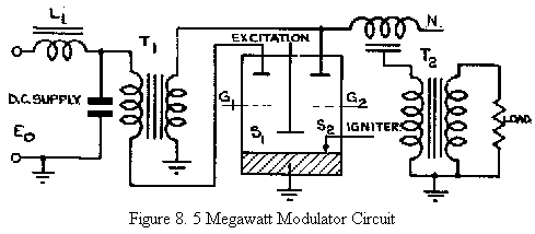
Eo = D.C. supply of 450 volts at 15 amps.
L1 = charging choke for input condenser C1. 0.3 Henry at 15 amps D.C.
C1 = input condenser. Capacity 16 μf at 1500-volts working. 30 amps RMS at 1 Kc/s.
T1 = modulation transformer turns ratio 1:25 (L2 1.5 mH) (L3 80 mH)
V = Modulator Valve nominally rated for 5 Kw mean power at a hold-off voltage of 20 Kv.
N = pulse-forming network. Zo = 20 ohms, pulse length = 2 μsecs, working voltage 20 Kv.
T2 = pulse transformer 1:5 voltage step-up to deliver an output voltage of 50 Kv. into a 500 ohms load impedance. Pulse length = 2 μsecs. Pulse repetition frequency up to 500 c/s.
This circuit has been used to deliver a peak output variable up to 5 megawatts at a pulse length of 2 microseconds and any p.r.f. up to 500 c.p.s. Unlike modulators using the air-blown triggered spark gap or the trigatron type valve, there is no difficulty in reducing the output power to a very small fraction of its maximum value by reducing the supply voltage, a feature which becomes of importance for very high power operation where gradual "running up" is often very desirable.
There is no evidence with the existing arrangement that the rate of pulse build-up is significantly limited by the modulator valve, and the stability of triggering is very high indeed, being certainly less than 0.05 microseconds. The trigger signals for G1 and G2 can be identical in waveform and separated by an adjustable interval which can be lined up for optimum operation and will not, in general, exactly equal the network recharge period t2. We shall now consider in rather more detail the effect of varying the delay between the two trigger signals about a mean value t2 = π√ L2 • C1C2/C1+C2
We have already seen that delaying the triggering of the secondary switch portion of the modulator valve-might be expected, within limits, to give no change of output. This is true, but it is found in practice that the stability of operation decreases as the delay is increased and finally the excitation arc is extinguished and the modulator cuts out. The explanation of this phenomenon, which is contrary to what might be expected from elementary circuit considerations, is apparently that the enormously rapid build-up of the main discharge current in the high voltage part of the valve robs the excitation arc of its supply of electrons, to such an extent that it is actually "blown" out. On the basis of this explanation, we might expect the valve itself to operate most stably with a slight advancement of the secondary trigger signal relative to the current zero of the primary section, in this way making use of the primary discharge as an excitation for the secondary one. This effect is observed in practice provided that the advancement is not too great when complete loss of control results. It is desirable, then, to operate the valve with an advancement of secondary trigger, which, for the circuit parameters as given, may be up to 100 microseconds in 400. It can be shown theoretically, and demonstrated practically, that progressive advancement of the trigger time of the secondary limb causes an adjustment in the operating conditions of the circuit and results, for a given supply voltage, in higher input current and correspondingly higher output voltage and power. This is useful since it enables control of the output power over a range of about 40% by variation of a potentiometer in the pulse generating circuits.
From present measured figures and from a knowledge of what component improvements can be expected, it appears that an overall conversion efficiency of the modulator of at least 75% should be obtainable. This compares favourably with other types in common use at lower output powers.
4. Applications to Higher Power
The mercury pool type of modulating valve lends itself to use at higher peak powers; it is possible to increase both the hold-off voltage and the peak current ratings by further development work. As far as the current rating is concerned, some idea of the possibilities can be seen from the fact that the existing valve has been used satisfactorily for an output of 50 megawatts corresponding to a peak discharge current of 5000 amps. In order to keep within the
mean power rating of 5 kilowatts, the p.r.f. was dropped to
50 c.p.s. The circuit used was similar to that already described, but with a network of 2 ohm characteristic impedance or ten times its original capacity, other
parameters being correspondingly adjusted. There is little doubt that the mean power rating of the present switch could be increased many times if more effective cooling were used.
It is evident that in considering development of this type of valve for much higher powers, increases of hold-off voltage and peak current ratings should go together in order to avoid the use of very low impedance pulse-forming networks. Furthermore, if higher powers are to be accompanied by higher output voltage requirements, as seems likely, then an increase of modulator valve hold-off voltage will be necessary in order to avoid excessively high-ratio pulse transformers.
On the circuit side, it may become desirable, in the interests of overall conversion efficiency, to raise the D.C. supply voltage and thereby avoid excessive primary currents. The present figure of approximately 500 volts D.C. has been used in order that the modulator can be fed directly from a D.C. machine of conventional design. The use of a machine for the D.C. supply has the advantage that the output can be readily controlled over a very wide range and, furthermore, the charging inductance L1 for the input condenser can be provided in the generator itself for some applications.
So far we have said nothing about the limitations of the mercury pool modulator valve in respect of maximum p.r.f. The valve was designed for up to 500 c.p.s. operation and has been operated satisfactorily in the same circuit up to 1500 c.p.s. by suitable adjustment of the circuit constants. Although no life test data is available to confirm, it appears that it should be satisfactory at frequencies well above its nominal rating. At 500 c.p.s. lives of the order of several thousand hours have been obtained.
Taking in account these various considerations, the following tentative specification may be drawn up for a higher power valve of the same general type; it does not represent the limit, but appears to be a reasonable step from the present rating.
Peak output power 50 megawatts
Hold-off voltage 60 kilovolts
Current in Secondary limb 1600 amps peak.
Mean power output 40 kilowatts maximum.
Maximum p.r.f. 1250 c.p.s.
5. References
TRE Report No. T.2088 Some Considerations affecting the Use of Reverse Diode Protection on Modulators using D.C. Transformation Charging.