1. Introduction
While the initial experiments on H2S were going on in this country very little interest was shown in the U.S.A., for the main reason that they had developed their optical bombsights and did not envisage any operations in which these could not be used. A number of flights were carried out by members of BAC and the Radiation Laboratory as H2S experiments but for some reason never fully explained they did not reproduce the results obtained in this country.
The main interest was centred on ASV and the first centimetre ASV fitted aircraft (Dumbo) arrived at Hurn about March 1942 and demonstration flights wore given. The equipment was known as DMS 1000 and twelve of these sets fitted to Liberators went into operation with Coastal Command round the beginning of 1943. These were used for daylight operations only, as the aircraft were not fitted with Leigh Lights. These few sets were not satisfactory from a maintenance angle, never having been fully engineered and they were superseded by ASG-1 (ASV Mk.V), which began to be used operationally about the same time as ASV Mark III. Once again the equipment was used only in daylight. Since that time many squadrons of Coastal Command have been converted to Liberators fitted with ASG-1 or AN/APS-2 (ASV Mk.Va) and lately Leigh Lights have also been fitted. The VLR (very long range) aircraft operating from Northern Ireland, were used for protecting the Atlantic convoys, flights of up to seventeen hours duration being common, with the aircraft often nearer to American than its home base. The LR Liberators were used in the Battle of the Bay. Other American ASV sets coming into use by the RAF or FAA are the AN/APS-15, AN/APS-3 and AN/APS-4. These are all X-band equipments.
When the U.S. VIIIth Bomber Command started operating from this country it soon became clear that they could not rely on their optical bombsight if they were to operate on more than a few days in the year. As a first step a number of their aircraft were fitted with British H2S equipment. Meanwhile work was started back in the States on developing their own H2S. This originally was called the hybrid ASD/ASG, being mainly composed of various components from these two systems. Subsequently, as the equipment developed it received the official label of AN/APS-15, but continued to be known to all as H2X (equals the British H2S Mark III). The first few H2X aircraft went into operation with the VIIIth Bomber Command in October 1943 and since that time the number of fitted aircraft (both Liberators and Fortresses) has grown to several hundred, with XVth Bomber Command operating from Italy, also using the equipment on a large scale. There is a similar equipment known as AN/APQ-13, which is the Western Electric version of H2X (APS-15 is made by Philco); this is fitted in the B-29 Super-Fortresses operating in the Far East.
A number of Pathfinder Liberators with APS-15 will shortly be going into service in the RAF, in the Mediterranean and Indian theatres.
A brief outline of, future American H2S/ASV is given at the end of the article.
2. AN/APS-15 (H2X)
The components used in this equipment are shown in this schematic.
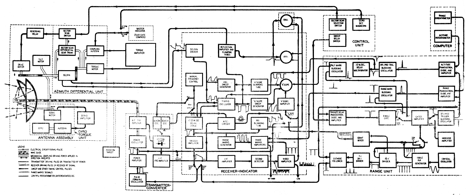
(a) Scanner This is the now familiar barrel insert, cosec2
type. It differs from the British scanner in that the feed is from the back of the mirror. Variable tilt is provided, the feed moving with the mirror necessitating the use of the two rotating joints. There is an alternative barrel insert for low altitude ASV work. The feed consists of a tapered waveguide terminated by a double window flat horn. The whole of the RF plumbing is pressurised for high altitude operation. Provision has been made for tilt stabilisation but to date this has not gone into operation. Sector scan can be used and, as in the British scanner, an indication of aircraft heading and azimuth stabilisation are provided.
(b) Azimuth stabilisation The gyro flux-gate compass (equivalent to the DR compass) drives, via the Torque amplifier, the stator of the selsyn which feeds out the azimuth information, thus keeping north always at the top of the PPI. Apart from the differences caused by the use of another type of remote indicating compass the system is exactly similar to the British.
(c) Transmitter-Converter The modulator, transmitter, and associated plumbing and the IF head amplifier are combined in one unit.
The modulator is the standard so-called Navy modulator. Pulse width is determined by artificial lines and the final drive is by a single hard valve (715B) rated at 14 kV 15 amps. The magnetron is the 725A which has a peak output of approximately 50 kW. The magnetic field is about 7500 gauss. The local oscillator is the 723A/B and the 1B24 is used for the TR and ATR cells. The modulator is enclosed in a cylindrical finned can and pressurised. Repetition rate on search is about 600 cycles per second with a one microsecond pulse; on precision ranging and bombing (see later) the repetition rate is 1155 cycles per second with a half microsecond pulse. Facilities are provided for interrogating X-band beacons, use of which is standard American policy. There is a two microsecond pulse output (the beacon discriminates against shorter pulses to avoid over-interrogation by normal search radars) and a separate beacon local oscillator. Ranges of over two hundred miles are obtained on beacons if the aircraft is flying above the optical horizon from the beacon.
(d) Receiver-Indicator As its name suggests this is a combined unit equivalent to the British waveform generator plug indicator and power supplies (EHT is in the modulator). This of course cuts down the number of cables necessary, but makes the unit rather large for easy handling.
There are two cathode ray tubes, a 5FP7 5" PPI all magnetic long afterglow, and the other an electrostatic 2 inch short afterglow (the "A" scope), the latter acting as a height tube and also, with the appropriate switching, as a monitor. An open-centre control is provided, although this is used only for ASV work.
The other controls are:
Most of the switching is done in this unit:
There are also a number of pre-set screwdriver controls.
Three meters are fitted, for indicating tilt, crystal current and transmitter current.
The receiver circuit is quite normal, there being five stages operating at an I.F. of 30 megacycles. AFC is incorporated. There is a single video stage driving a cathode follower output. On search, the range unit is not used and the initial timing is performed by the timing oscillator in the receiver indicator. This triggers the sweep generators, blanking circuits etc. and after passing through a delay stage (variable from 12 to 25 μsecs) and an amplifier, triggers the pulse-forming oscillator in the modulator. The object of the delay stage is to fire the transmitter at a time later than the beginning of the sweep, and thus avoid the non-linear part. It also acts as an open centre control.
(e) Range Unit For precision ranging and bombing the range unit provides the initial timing signal, a crystal oscillator, generating pulses at 80.86 Kc/s. Divider circuits count down to approximately 1100 cycles for driving the transmitter. Two circuits produce one and ten mile pips which can be fed to the "A" scope for calibration purposes. The output of the divider circuits is used to trigger the range and altitude phantastrons which in turn trigger their respective blocking oscillators from the output of which are derived the range and height markers. The range marker operates out to 15 nautical miles. For ranges beyond 15 miles further circuits are introduced which delay the triggering of the phantastrons in ten mile stops up to a maximum of 215 nautical miles. This function would normally only be used with beacon returns.
For bombing, the procedure is similar to that used in H2S. The altitude pip is set to the beginning of the ground signals and the computer drum rotated until the cursor which is coupled to the altitude adjusting knob lies over the previously determined ground speed. The range marker will then appear on the PPI at a slant range calculated to give the correct horizontal forward travel for the bomb.
(f) Computer This unit contains the chart for bomb release calculations. There are two main controls, the range knob and the altitude knob. There is an on-off switch for the range marks and a dial light intensity control. The chart, which can be changed if necessary, is mounted on a drum controlled by the range knob. There is a potentiometer coupled to the drum for varying the voltage on the anode of the range phantastron in the range unit. Similarly, the altitude knob, which moves the
altitude cursor across the chart, is coupled to a potentiometer varying the anode volts on the altitude phantastron.
(g) Control Unit The rest of the controls and switches are on this unit. They are:-
There is one screwdriver control for setting the lubber line.
(h) Performance Ranges of 40-50 miles on, medium-sized towns are obtained regularly with greater ranges on towns of the size of Berlin. Painting usually extends to about 25-30 miles. The polar diagram is not completely satisfactory at steep angles and the absence of ground range sweeps tend further to spoil the picture near in. In later models ground range sweeps will be provided. The equipment seems to be very reliable from the maintenance angle, averaging around 90% sorties serviceable over the target.
3. A.S.V.
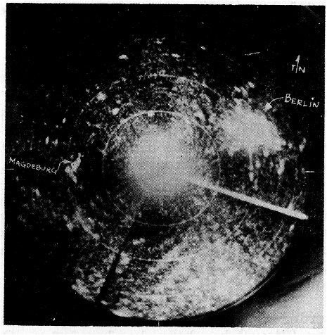
Figure 41 A PPI photograph of Berlin taken at 20,000 ft Berlin is at 30 miles
(a) AN/APS-2 (ASG-3) The ASV equipment in most common use
in both the RAF and the US Air Force is the S-band AN/APS-2
(formerly ASG-3). This set has undergone several changes
since its original introduction as ASG-1, but basically it
remains the same. It differs from the usual conception of a radar set in that instead of a large number of small units with many interconnecting cables, it consists essentially of
two units only, plus the antenna system. These units are
the transmitter-converter (which includes the modulator)
and the receiver indicator. Outwardly these resemble the
corresponding units in AN/APS-15, which started life as an ASW/ASG hybrid (see above). The transmitting magnetron is the 2J22, which has a peak output around 50 kW. The output line is stub-supported 50 ohm concentric and again the scanner has two rotating joints to allow for both rotation and tilt. The local oscillator is the 417A tuned from the operator's position via Bowden cable. The latest model AN/APS-2F which completes the APS-2 series, has a new
local oscillator (2K28) and AFC. In this series a control unit similar to that in AN/APS-15 is fitted.
The basic circuitry of the modulator is the same as the AN/APS-15 model as is also that of the receiver indicator. The main difference in the latter unit is in the I.F. strip which has a much narrower band (approximately 2MC) and is without AFC. The controls on the R-I panel are mainly as before with one or two, such as the scanner control switches added (in the models without a control unit).
Centimetre beacons can be received on switching over to the beacon position. This alters the tuning of the local oscillator and changes the pulse length to two microseconds, as the American centimetre beacons discriminate against short pulse length to avoid over-interrogation by normal search equipment.
In order to counteract, enemy listening tactics an R.F. attenuator (Vixen) has been developed for attachment to APS-2. The attenuator is motor driven (not manually controlled) and the attenuation varies approximately as the reciprocal of the range cubed. This gives a constant or slightly decreasing average signal on the listening receiver. It was felt that automatic rather than manual control was to be preferred as the action would be a little smoother (there is no advantage in a jerky motion as the signal varies over wide limits in any case) and more important, should the signal vanish momentarily the operator is not able to wind the attenuator back and ruin the whole scheme. Briefly, the procedure is that the navigator, knowing the aircraft's ground speed, tells the radar operator when they are four minutes away from the target. At this point Vixen is switched in. As designed there should be no danger of losing the signal completely for even at maxim attenuation the beam-on range on a U-boat is about 2½-3 miles (i.e. a margin of one minute's flying time). The preproduction Vixens (AN/APA-22) pulled the magnetron frequency and made it necessary to retune the local oscillator during the run-in.
This is a very bad fault which it is hoped will have been remedied in the production models. In the meantime, a matching transformer between the magnetron and the Vixen t move the working point of the magnetron to a position where frequency pulling is considerably reduced has been tried successfully without any noticeable loss of range. The production models incorporate such a transformer. The AN/APS-2F with AFC will, of course, provide a complete solution.
No operational experience is yet available on Vixen to show whether it is successful in hoodwinking the U-boats.
Performance Average operational range on submarines in Coastal Command is around 15 miles compared with 10 miles on ASV Mk. III. Ranges of up to 8 miles have been obtained in recent operations on Schnorkel, a "breathing tube" which enables the U-boat to proceed on Diesels while submerged. Reliability is good, being about 300-400 flying hours per fault over the whole Command.
(b) AN/APS-3 (ASD-1) This X-band ASV set is being fitted to Catalinas. One squadron being already operational at Sullom Voe. The action which gained a Coastal pilot the V.C. was the result of an initial radar contact on this equipment.
The main difference between AN/APS-3 and the majority of search equipments is in the presentation, which is Range-Azimuth (B type) not PPI. This has an advantage in homing on to a target but makes map reading difficult owing to the distortion introduced.
There are eight units: (see Fig. 42)
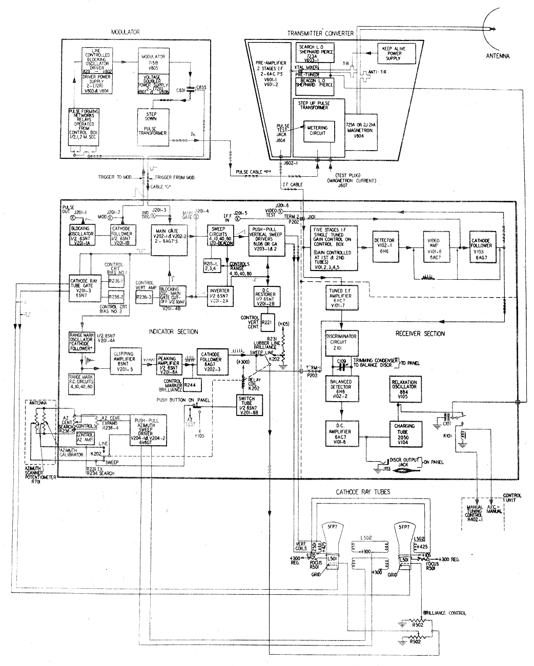
Figure 42.
(i) Scanner The dish is 18" in diameter fed from the back by a tapered waveguide terminated by a dipole and reflector. Polarisation is horizontal. The coverage 150° in azimuth at about 35 cycles per minute. There is a 2° nod on the azimuth sweep to cover a larger field for any setting of the tilt control. This control can be varied between ± 8°, but as the reflector alone moves, the dipole remaining fixed, the resultant electrical coverage is approximately 24°.
(iv) R.F. Head This is equivalent to the British T2R, and contains the magnetron (725A), the local oscillators (723A) etc., the pulse transformer and head amplifier. The electrical design is similar to the R.F. portion of the AN/APS-15 apart from the pulse transformer. It is shaped to fit behind the scanner in a streamlined nacelle.
(iii) Modulator This is fundamentally the standard "Navy" model except that a transformer feeding a low impedance line to the R.F. head replaces the direct connection to the magnetron as in the AN/APS-15 system. The original equipment, known as ASD, had the APS-15 type of combined transmitter modulator; in certain installations where the scanner was located out on the wing a long waveguide run was required. This was undesirable, particularly for carrier-borne aircraft where it was necessary to break the wave guide at the wing joint.
(iv) Control Unit All the controls and switches are located on this unit making life much simpler for the operator.
These controls are:-
There is also a meter which indicates the tilt setting.
(v) Indicators Two indicators are provided, each with its own focus and brilliance control. As there are no other controls the unit is little more than a housing for the 5FP7 5" CRT and its deflection and focusing coils.
(vi) Rectifier Unit This power pack supplies all the required voltages except the E.H.T. which is included in the modulator. These voltages are +4500V for the CRT, +425V, +300v. (regulated and unregulated) +105V. regulated, -255V. regulated and -105V. regulated.
(vii) Receiver-amplifier This is a combination of timing unit, waveform-generator and receiver. The primary oscillator is a blocking oscillator which provides a pulse for triggering the modulator. In turn a pulse from the modulator triggers the vertical sweep, the range mark, and CRT blanking circuits. The azimuth search push-pull amplifier is driven from a potentiometer on the scanner.
The range mark circuit consists primarily of a ringing circuit in which the inductance is switchable for various range mark values.
The ranges available are 4, 10, 40 and 80 n.m. on Search, on beacon the 80 mile range is extended to 120. The range marks are every half mile on the 4 mile sweep, 2 miles on the ten mile sweep, 10 miles on the 40 mile sweep, and 20 miles on the 80 and 120 mile sweeps.
In the "expand" position the azimuth sweep is spread out so that ± 30° about the zero fills the screen. A lubber line (adjustable in position by the azimuth calibrator) is also available in this position. The object of the "expand" function is to make homing easier and more accurate. The B scan in any case is superior to the PPI for accurate homing except possibly when an open centre control is fitted to the latter and the expanded sweep improves the performance.
The receiver proper consists of five 30 Mc/s I.F. stages, diode detector, video amplifier and cathode follower output and AFC is used. It is on this receiver that the APS-15 receiver is based.
(viii) Azimuth calibrator This sets the position of the lubber line (in the "expand" position) thus enabling the azimuth bearing of a target to be read off accurately.
Performance So far there has not been a great deal of operational experience but CCDU trials were extremely encouraging, ranges of approximately thirty miles being obtained on a submarine beam-on. In tests on a corner reflector APS-3 gave an average range of about 12 miles compared to 4-5 miles on Mks. III and Va (S band).
So far no major maintenance troubles have occurred.
(c) AN/APS-4 (ASH) The Fleet Air Arm are embarking on a big installation programme of ASH in Firefly and Barracuda aircraft. The Firefly installation is for AI and not ASV.
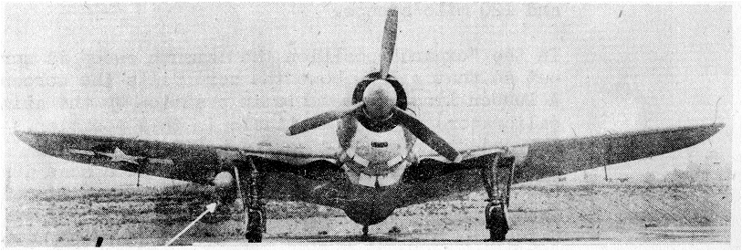
Figure 43. AN/APS4 on Avenger
The chief merit of the equipment is its size and weight, as it is the first attempt at a lightweight miniature set to go into production. The majority of the equipment is contained in a "bomb" approximately 60" long and 17" in diameter (Transmitter-Receiver unit). This is slung externally under either the fuselage or the wing (Fig. 43) and is connected by a multi-core (27) plug and cable to the rest of the installation in the aircraft. This plug is arranged to separate quickly as it is part of the specification that the "bomb" be capable of being jettisoned. The F.A.A. installation does not make use of this facility. In the aircraft are one or two indicators for single or twin seaters, their respective indicator-amplifiers (unit size approx. 3¾ x 6½ x 7½", junction box 3½ x 11¾" x 5½) and operators control box (2¼" x 6" x 7 1/8"). Apart from a brilliance control on the indicator, all the controls which the operation need use in flight are, as in the APS-3, on the control box.
The total weight of the equipment is approximately 175 lbs. (plug cables and power supply).
The complete system is shown in the photograph (Fig.44)
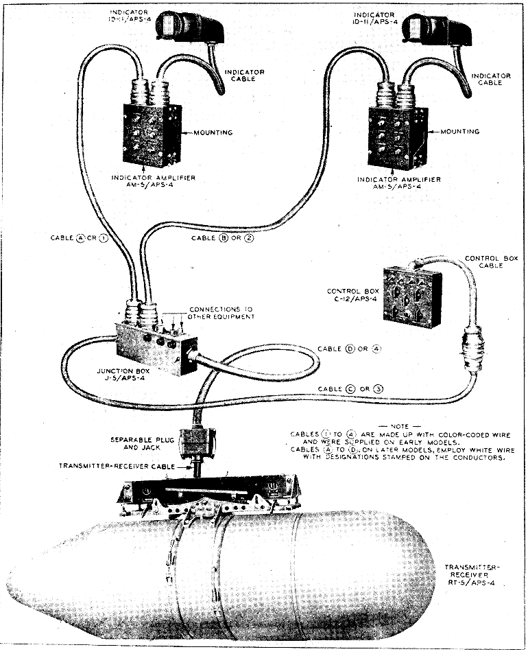
Figure 44.
(i) Transmitter receiver This "bomb" unit contains the scanner, transmitter circuits and associated plumbing, receiver circuits, high and low voltage rectifiers and the range and alarm unit.
The scanner consists of a 14" parabolic dish fed from the back by a fixed horn. The azimuth sweep is ± 75° and the elevation coverage on search is approximately from +13° to -37°. On search the dish is oscillated to give a 4° two line sweep, rather similar to APS-3, the limits of the top line being from +10 to -30°. The beam width is about 6°. On intercept (for AI work) a four line sweep is provided with 6° between lines, the bottom line being at the tilt control setting. On search there are 30 two-line frames per minute and on intercept 30 four line frames.
The transmitter uses. the 725A magnetron, 724A TR and ATR cells and 726A local oscillators. A "sea-cock" is at present fitted in the waveguide between the transmitter and the scanner. The idea of this is that by opening the "sea-cock" a small amount of RF energy is radiated vertically downwards; this can be used as a check that the equipment is functioning. In practice the spill over already there produces strong altitude signal without having to use the sea-cock. The other use is to enable the TS-45 X band test set to be attached for ground checking.
The modulator is of the triggered spark gap type using two 1B22 valves. An interesting point is that switching of the pulse length line for beacon long pulse operation must be done at high-voltage in this type of modulator and a special high-voltage relay is used. The repetition rate is 1000 pps (0.6 us pulse) on search (600 pps on the 100 mile range), and 350 pps on beacon (2 us pulse).
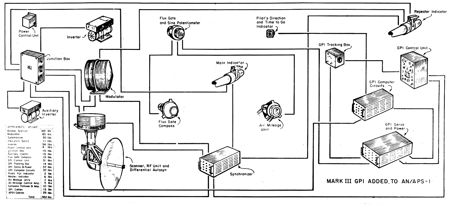 Figure 45.
An oscillating multivibrator controls the multivibrator which produces the modulator trigger pulses. These are amplified in two stages and applied to the series spark gap. The pulse formed by the discharge of the delay network is stepped up by a pulse transformer and fed directly to the magnetron.
Trigger for the range sweep circuits is taken off a small resistance in series with the spark gaps and after differentiation drives a multivibrator. This latter also drives the range mark circuits.
The 60 Mc/s I.F. amplifier consists of five stages plus a two stage head amplifier. Band width is about 4Mc/s. Gain control is obtained by varying the anode and screen volts on the first three stages (not including the head amplifier). A pedestal for CRT blanking is mixed in at the video amplifier stage, which drives a cathode follower output. AFC is provided, including an automatic sweep of the beacon local oscillator.
The alarm circuit is designed mainly for use in single seater aircraft in which the pilot cannot give as much attention to the CRT as an observer in a two-seater machine. The circuit lights a lamp on the control panel if any target appears at a range beyond that set up on the alarm blanking potentiometer. The latter control is necessary to avoid triggering of the circuit be sea returns. It is not certain that the alarm has any operational value.
There is a control amplifier for setting the tilt limits according to the setting of the tilt control. This fixes the top line on search and the bottom line on intercept.
There is a "double-dot" circuit which is used on intercept for elevation indication.
(ii) Indicator amplifier This contains a push-pull amplifier for the vertical sweep together with fix pre-set controls. There are:-
(iii) Indicator The CRT is a 3" 3FP7 long afterglow tube with electrostatic focus and deflection. There is a final push-pull video amplifier with DC restoration.
(iv) Control Unit On this unit are:-
There is also a screw-driver control for setting the tilt zero.
Performance There are no operational results to date but satisfactory ranges on ships and coastline have been obtained in trials. As in AI, the maximum range on a Firefly target is 3-3½. n.m.
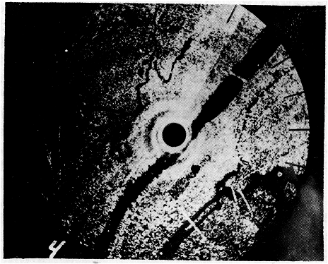
Figure 46. Height 8000 ft - 2 to 7 mile sweep. Docks at 7 o'clock. Central Park and Lake at 5 o'clock.
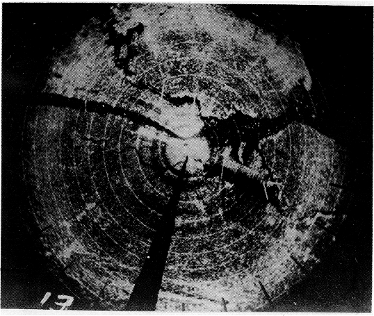
Figure 47. Height 16,000 ft. Docks at 9.30. Central Park and Lake at 10 o'clock.
4. Future Equipments
Originally a universal H2S/ASV set called AN/APS-1 was proposed and started but the conflicting requirements of the U.S. Army and Navy have now caused a change in plans. The Navy are to have the APS-30 series which will be on either X or K bands and will have either 360° WI or 180° range-azimuth presentation. These sets will incorporate all the latest techniques in sea-return discriminators etc. The K-band heads will use the 3J31 "Rising Sun" magnetron and 2K33 "Oxford" local oscillator which are in the Sylvania R.F. head for H2S Mark VI. The army are to have the APQ-34 which corresponds very closely to H2S Mark VII. It is a K-band equipment (made by Western Electric) with a new "package" K-band magnetron and Neher local oscillator. A GPI which is similar to the NBC computer of Mk. -VII is part of the system (Figure 45). So far only experimental flights have been made and two photographs taken at 8000 and 16000 feet over New York are shown (Figs. 46 and 47). These were not taken on the APQ-34 but with the APS1-K (as
it was originally called), i.e. H2K or H2S Mk. VI. The excellent definition obtained (see especially the docks) offers the possibility of high-precision bombing. This particular set used a 42" scanner and a ½ μsec pulse; with the new 6 ft. array and shorter pulse, definition on the British K-band should be even better than this. "Painting" out to 20 miles from 20,000 ft. has been achieved to date on the laboratory model and it is hoped that there will be sufficient improvement in the RF side to make this an average operational figure.
There is another set, designated AN/APS-10 or "the poor
man's set". This was originally intended to weigh only
75 lbs but looks like being round about the 100 lb mark.
It corresponds to the British light-weight ASV.
The scanner has an 18" dish, cosec2 for 5000 feet, with variable tilt. There is a combined transmitter, modulator, receiver, and power supply (the XMTR) using a low-voltage "package" X-band magnetron (the 2J42) and a hydrogen thyratron (3C45) modulator. The indicator has a 5" long afterglow CR tube and there is a separate unit for the indicator power supply. The controls are combined on a single unit called the Indicator Central and Control Panel. It is hoped that production will begin in January 1945.
An interesting development is the AN/APQ-7, better known as "Eagle", The unique feature of this equipment is the sixteen foot linear array housed in an auxiliary vane under the nose of the aircraft. The beam width is two-fifths of a degree and is swung electrically over plus and minus thirty degrees. The swinging is carried out by altering the wide dimension of the wave guide feeding the array of two hundred and fifty dipoles. This gives a thirty degrees movement from zero to plus thirty; the other thirty is obtained by changing the feed to the other end of the array by an R.F. switch. Pulse length is three-eighths microseconds. The rest of the equipment is quite orthodox.
Resolution is very high due to the large antenna aperture. Ranges of up to one hundred miles on large cities are common, with "painting" out to forty or fifty miles. Railway marshalling yards, docks and other small targets can be picked out. The limitation of the system is, of course, in the azimuth coverage; whether this is serious operationally remains to be determined.
There is one B-17 at Alconbury about to begin operational trials; a B-24 is due to come to TRE about the end of December.