1. Introduction
The original S band version of H2S was developed on a "Crash" programme basis and, in order to allow quantity production to start as soon as possible, the complexity of the equipment was kept down to a minimum; in particular the PPI display arrangements were simple and straightforward. Subsequent Marks of the equipment, the Mark II series on S band and the Mark III series on X band, have all used basically the same design of units, and, while new ideas have been introduced in these later systems, they have been developed along lines which would enable them to fit in readily with the existing equipment.
H2S Mark IV, on the other hand, was from the beginning conceived as an entirely new version of H2S the design of which, except in its relation to such standard units as Modulator and Power Unit, etc. was not required to conform either physically or electrically to techniques used on the earlier systems. The operational requirements of the equipment were, of course, fundamentally the same as before, namely navigation and blind bombing facilities, but in the case of Mark IV the emphasis was on the latter of these. It was intended that those ideas which lack of time had prevented from being incorporated in the original equipment should be introduced in Mark IV, together with any further major improvements found desirable as a result of operational experience with Mark II. Mark IV was to be an X band equipment for large scale production, to be fitted in both PFF and Main Force aircraft.
Two specific requirements were however made. In the first place, where standard units could be used they were to be those which were being developed for the Universal Units programme, and secondly, the equipment was to link up with the Mark XIV Bombsight, which was to be a standard fitting in all heavy bombers, with the object of presenting on the display all the information required for accurate blind bombing. The extent to which these requirements have been met is described later in this article.
2. General Description of the Mark IV Equipment
(i) The RF System
Considering first the R.F. side of the system, the R.F. unit is the TR 3523 the distinctive feature of which is that it provides automatic frequency control of the local oscillator; remote manual tuning is also available. The peak power output is in the region of 35 kilowatts and the pulse width ½ µsec. as distinct from the 1 µsec. used on previous equipments; radial definition is thus improved. To compensate for the reduced pulse width the pulse recurrence rate is increased to a nominal 1000 c.p.s., thus allowing a maximum scan time on the display of approximately 800 µsec. corresponding roughly to 80 miles. The modulator is self running, all units being synchronised to it by a 20 µsec. pre pulse.
The Scanner is in most respects the same as the one used on Mark IIIA, a barrel type, roll stabilised over ± 30°. In this case however the magslip resolver has been replaced by a sine Potentiometer, a Universal Unit with the official title of Waveform Generator, providing D.C. voltages proportional to sin α and Cos α, where α is the azimuth angle of the beam. Voltage waveforms in quadrature are derived from these sin and cos α voltages and applied to the deflecting plates of a 4 kV electrostatic CRT to produce a rotating time base synchronised to the scanner rotation. The Scanner speed is variable over limits of approximately 30 to 70 r.p.m.
Scanner tilt control is introduced for the first time with Mark IV. The importance of this feature has been described in the article on the H2S aerial problem.
(ii) Display System
There has been considerable elaboration of the display arrangements compared with the earlier equipments. The most urgent need was for an undistorted ground range presentation particularly on the short range scan. This has been provided and at the same time it has been arranged that the necessary correction for height is done automatically. Having then obtained an undistorted ground range picture the next step was obviously to make the PPI range scales agree with the scale of maps used in the Service so that the picture seen on the PPI was an exactly scaled representation of an area on the appropriate map. Thus the four PPI scan ranges on the Mark IV Indicator correspond to map scales of 1/4, 1/8, 1/16 and 1/32 inch to the mile, that is the 1/4, 1/2, 1 and 2 million series.
Having thus provided a true map picture on the display it then became possible to dispense with the adjustable electrical range marker as used on Mark II and Mark III, this being a considerable saving as it avoids the need for the somewhat elaborate range potentiometer drum of the old Switch Unit. Ranges can now be measured directly off the PPI with the aid of dividers and plotted straight on to a navigation chart. As an alternative it is also possible to measure range on the Mark IV equipment by means of accurately calibrated controls which shift the whole picture along the two axes of the CRT, corresponding to N/S and E/W axes, these controls being provided primarily for the purpose of off-set bombing.
Returning to the subject of distorted scan, as has been explained in a previous article, the distorted picture results from the fact that a linear scan is used which is correct only for zero height and at any finite height gives a true representation of slant range, or slant range minus height on the 10 mile range, but a distorted picture of ground range. To present an undistorted ground range picture it is first necessary to delay the start of the scan by an amount equivalent to the height of the aircraft above ground and then to make the scan start rapid and run in exponentially to the form it would have had in the absence of any correction, in other words a hyperbolic waveform is required. The amount of correction required depends of course on height so that for every height a different hyperbola is necessary. The method by which this is done automatically on Mark IV is as follows.
Electrical height is measured automatically by means of a drifting strobe, corresponding to the manually controlled height marker on Marks II and III, which, starting at a time after the transmitter pulse equivalent to approximately 2,000 ft, searches out to a height of about 30,000 ft. If there is no signal present over this range of heights the strobe returns and repeats the cycle automatically; in the presence of signals however the strobe will lock on to the first one it encounters, which will in practice be the leading edge of the ground return from immediately below. The mechanism of this height following strobe consists of a strobe pulse generator triggered at a time after each transmitter pulse controlled by the anode potential of a slow speed Miller valve. The height marker pulse thereby generated occurs at a time after the transmitter pulse which increases as the anode of the Miller valve runs down. A diode bridge arrangement, gated by the strobe pulse, rectifies the signal returns and feeds current into the feedback network so as to oppose the normal rise of grid volts. The anode run down thus stops at a potential determined by the time after the transmitter pulse at which the first signal appears, i.e. by the height of the aircraft above ground. The strobe pulse therefore stops drifting and remains locked on to the leading edge of the ground returns. In addition to generating a strobe or height pulse, a positive going pulse is produced from a multivibrator which is turned on at time 0, i.e. the back edge of the 20 usec pre-pulse, and is turned off at a time again determined by the anode potential of the Miller valve, in other words by the height. This positive going 0 - h waveform, as it is called, is differentiated and applied as a synchronising pulse to the scan multivibrator controlling the display scan time and which is arranged to trigger only from the negative going portion of the differentiated 0 - h pulse. Thus the start of the scan is automatically delayed for a time equivalent to the height of the aircraft. The next step is to make the scan waveform hyperbolic, the shape of the hyperbola being self correcting for height. This is done by first producing a saw-tooth waveform, starting at time h, for each axis, by charging a condenser through a resistance from the sin α or cos α potential, the maximum charging voltage being approximately 20 times the maximum saw-tooth potential, in other words the charging can be considered as due to a constant current, and then adding into this linear scan extra charge from a network charged up during the time 0 - h. This correction network consists of a geometric series of resistance and condenser elements, each branch consisting of a resistance and condenser in series. The number of branches used determines the accuracy with which the required distorted waveform is reproduced. The rate at which extra charge is added is controlled by the individual component in the correction network, while the total amount contributed is controlled by the R/C ratio in each branch.
The provision of automatic height correction as described above renders unnecessary a separate 'height' CRT. On previous equipments this gives a range-only presentation which is used for obtaining information on height by manually setting a marker pulse against the leading edge of the first ground return and reading off height on a calibrated scale; in addition it is used for tuning purposes. These operations are done on a separate tube in order that the PPI picture be maintained at the same time, as opposed to having the range only presentation on the main tube with consequently the disadvantage of having to switch from the PPI picture when height setting and tuning. Both these operations however are automatic on the Mark IV equipment, so that a separate range display is unnecessary. At the same time provision is made on Mark IV for manual setting of both height and tuning, should trouble be encountered with the automatic controlling circuits, so that a range only display is provided. In this case however it is presented on the main tube, and is selected by a switch when required.
(iii) Computer System
As was stated in the introduction the Mark IV equipment was required to link up with the Mark XIV Bombsight to assist
in blind bombing. This has been done by displaying automatically on the PPI the ground track of the aircraft, to an accuracy determined by the available wind information, and the point of bomb release. Considering first the track marker, this is displayed as bright radial line on the PPI, similar to the course marker. As has been explained in a previous article this course marker is derived from a cam and contact set on the scanner; the contacts are fixed and the cam is mounted on the rotor wheel of the magslip (or sine potentiometer as the case may be) which is driven in synchronism with the scanner. The contacts are made by the cam once per revolution of the scanner and an instant which can be manually adjusted to be the instant when the scanner is pointing dead ahead along the for and aft line of the aircraft. The PPI picture is north stabilised from the DR compass and so the bearing of the course marker always indicates the heading of the aircraft. The track marker is obtained from a second contact on the scanner which is variable in position up to ± 40° about the position at which the course contact makes. This variable contact is driven through gearing from an M motor controlled by an H transmitter driven from the drift angle shaft of the Mark XIV Bombsight Computer. This M transmitter is housed in a small unit attached externally to the Bombsight Computer intercepting the flexible shaft drives between the Computer and the Sighting Head in the nose of the aircraft. The gearing between the M transmitter and the track contact on the scanner is such that this contact is offset from the course contact by an angle equal to the drift angle of the aircraft as told by the Bombsight. The Bombsight computes drift having first had wind coordinates fed in to it manually, airspeed and course being automatically derived. Thus the PPI track marker will automatically display the aircraft's ground track, following any change in airspeed and course, but not, of course of wind.
Treating next the bomb release point display, this is presented as the intersection point of the track marker and a circle in the centre of the picture whose radius corresponds to the forward throw of the bomb in use, for the particular ground speed and height of the aircraft. The position of this bombing range marker is also automatically computed and displayed, from information again obtained from the Mark XIV Bombsight. This computes what the bombing angle β is on a target for the height and ground speed of the aircraft and the T.V. of the bomb in use. If the height of the aircraft is h, then the slant range to a target is h sec β. It is thus required to produce a marker pulse at a time after time 0, the transmitter pulse, equivalent to h sec β. A voltage proportional to height is known (v.s.) and if this is applied across a potentiometer with a secant law calibration, the slider of which is driven from the bombing angle shaft of the Bombsight Computer, then the voltage on the slider will be proportional to h sec β. This voltage controls the time of a pulse generator so as to produce a marker pulse at a time after time 0 equivalent to h sec β. The start of the scan has been delayed until time h and so the time between the start of the scan and the appearance of the bombing marker is equivalent to h (sec β - 1), i.e. the difference between slant range and height. The distorted scan waveform now causes this marker to appear at a distance out from the centre of the scan corresponding to the ground range to the target i.e. the forward throw of the bomb. Thus at any instant the point on the ground as seen on the PPI, covered by the intersection of the track and bombing range markers represents the point of impact of a bomb released at that instant.
(iv) Stabilised Display
We now come to something new in H2S, namely the stabilised PPI display. This is first introduced with Mark IV and on this equipment it is derived from a computing system linked up to the Air Position Indicator (API) the Air Mileage Unit (AMU). The normal H2S presentation is one in which the ground as seen on the PPI is moving over the screen in accordance with the ground speed and track of the aircraft, while the start of the scan, representing the aircraft's position, is stationary in the centre of the tube with the bombing circle round it and the track marker originating from it. If now, shift voltages are applied to the X and Y axes of the CRT which are equivalent to the ground miles travelled by the aircraft on these axes i.e. E/W and N/S, starting from any reference time, and which are in the correct sense so as to oppose the normal movement of the picture, then from that time onwards the PPI picture of the ground will remain stationary while the scan will move over the tube face in accordance with the ground speed and track of the aircraft, taking with it in the case of Mark IV the bombing range and track markers. This type of display is called a stabilised PPI display.
The method used on Mark IV to obtain this stabilised display is briefly as follows. The combination of AMU and API, which are standard aircraft instruments, allows a continuous and automatic air plot to be maintained, the air position being recorded on counters in degrees and minutes of latitude and longitude. The AMU determines the true airspeed and passes this information to the API in the form of a shaft rotation, the speed of rotation being proportional to true airspeed. The heading of the aircraft, as determined by the DR compass, is fed into the API and used to resolve continuously into N/S and E/W components the air movement of the aircraft as measured by the AMU. Thus, starting from a reference time, the API indicates the air miles travelled N and E by the aircraft from that time onwards.
The API Mark IA, in addition to recording this information on counters, feeds it out in the form of M transmissions.
In the Mark IV Computer Unit are two stud potentiometers the sliders of which are driven through reduction gearing and spring loaded clutches from two M motors connected to the API drives. One potentiometer is associated with air miles N and 5, the other with air miles E and W. A balanced floating supply is applied across each potentiometer so that when in their rest positions the sliders are at zero potential. Then the API drive is applied the sliders describe positive or negative excursions, in terms of voltage, depending on whether the API drive is N or S in the one case, and E or W in the other. Thus starting from the reference time, potentials exist on the sliders which are proportional to the air miles travelled on cardinal headings from that time and these potentials are applied as shift to the deflecting plates of the CRT to produce the stabilisation. The gearing between the API drive and the sliders and the voltage limits on the potentiometers are chosen to give an exact correspondence between air miles travelled and the shift in miles recorded on the PPI.
In the absence of wind the air miles shift voltages will provide complete stabilisation of the display. To allow for wind however additional shift has to be applied, again in the correct sense, and a rate aided method of doing this has been used. A wind miles stud potentiometer, with the same balanced supply across it, has two sliders driven at the same speed in opposite sense by a constant speed ratchet motor. In their rest positions the sliders are at earth potential, the centre point of the potentiometer, and when driven describe positive and negative voltage excursions, one going positive to correspond to wind miles travelled on a N or E heading, the other going negative to correspond to wind miles S or W. The speed of the ratchet motor and the voltage limits on the potentiometers are chosen so that the voltages on the sliders if applied as shift to the PPI would move the scan by an amount corresponding to wind of 100 knots on each axis. Actually the voltages picked off by the sliders are applied across a pair of 'wind rate' potentiometers one associated with wind N/S and the other with wind E/W. These potentiometers are calibrated in terms of wind from 0 to ± 85 knots and are so padded that for any setting on the wind dials the correct fraction of the 100 knot wind voltages is picked off.
These are the wind voltages which are applied to the PPI as shift being added in with the appropriate air shift voltages. Thus if the correct wind components are fed in on the calibrated controls, complete picture stabilisation will result.
The advantages that can be derived from this type of display are obvious. In the first place it provides a method of measuring wind. The air shift voltages can be assumed correct within the limits of accuracy of the AMU, API, Computer potentiometer linearity, etc. but the wind shift voltages may not correspond exactly to the actual prevailing wind since ones knowledge of wind may not be better than that given by met. Thus the picture will not 'freeze' completely but will tend to drift. However, the extent to which it does drift over a definite period of time is a measure of the amount by which the wind set in differs from the correct wind. Thus measurement of the picture drift gives a corrected value for wind which should then give a perfectly stabilised display.
Assuming now a solidly stabilised picture further
possibilities are evident. In the first place it is not
necessary to see the signal return on the PPI from the target at the release point, provided it has been identified
some time previously. To appreciate the advantage of this at least the difficulty experienced on both S and X band in following an aiming point in a large built-up area into bombing range has to be understood. A large town is reasonably well defined in outline at ranges between roughly 7 - 10 miles and at these ranges the required aiming point can usually best be recognised. At shorter ranges the area does not show up as a coherent whole but starts to break up into individual signal returns from different parts of it, which, in general, cannot be correlated with the structure
of the area. Thus an aiming point selected at optimum range tends to become indefinite as it is approached. However,
given a completely stabilised picture the selected aiming point will remain stationary as the aircraft approaches it and if its position on the tube face is marked it is no longer necessary to try and follow the actual signal but
simply a case of flying the aircraft until the bomb release point lies on this mark. In practice the marking of the aiming point is done by shifting the whole picture by means of manual controls until the aiming point lies under the centre of the perspex face covering the tube, this point being marked by small cross lines. In addition to eliminating the necessity for closely following a PPI signal this type of display on a bombing run has the advantage that a fair degree of tactical freedom exists once the aiming point has been frozen. Three points are clearly defined on the tube, the aircraft's position, the bomb release point and the aiming point and these remain so irrespective of whatever evasive action circumstances may within reason, demand.
A further use of the equipment resulting from the provision of a stabilised display is off-set or reference point bombing of a target which gives no H2S response on the PPI. This is achieved by first stabilising the picture with the reference point under the cross wires and then shifting the scan bodily by means of accurately calibrated manual N/S and E/W controls by an amount corresponding to the coordinates of the required aiming point from the reference point; the 'hidden' aiming point will then be under the cross wires and, if the wind information is accurate, will stay there.
To sum up on the stabilised PPI display, it can be said that, in conjunction with the height corrected picture, it is the biggest improvement made yet on H2S towards increasing the accuracy of blind bombing of industrial targets. It is essentially associated with the bombing run and for this reason the time for which a stabilised display is available is limited to a maximum of 5 minutes; for a ground speed of 200 knots this allows 20 miles to be covered on the ground which is more than adequate for the final run in on a target. A switch under the control of the operator selects either the normal or the stabilised type of presentation.
Before ending a general account of the Mark IV display arrangements it should be mentioned that a subsidiary indicator, the Fishpond indicator is part of the equipment. It is hoped that the design and application of Fishpond indicators will be treated elsewhere in a future journal; all that need be said here is that the Fishpond used with Mark IV is of a newer and more self-contained design than used on earlier equipments, although the PPI presentation remains the same.
3. Conclusion
To conclude this article a short account of the flight trials and the results being obtained might be of interest. The object of the first series of flight tests, made during 1943 on S-band, was to study the improvement in the H2S picture resulting from the corrected scan and to this end a large number of PPI pictures of towns and coastlines was taken with and without the correction, for purpose of comparison. Scan correction was introduced first on the experimental Mark IV units although it has reached the Service first in the Mark IIC and Mark IIIA equipments. Photographs of corrected and uncorrected PPI pictures are shown in Figs. 19a and 19b. Figs. 34a and b show the high quality of presentation given by a properly adjusted Mark IV equipment.
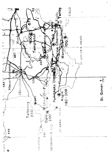
Preliminary tests were made of blind bombing accuracy to determine to what extent the presence of automatic track and bombing range markers improved results; most of the blind bombing tests have been done however with a later experimental set of X-band units, this being in several ways a more advanced set than the first, and, in addition, included the computing arrangements for the stabilised display, which the first did not. As a target for bombing a small island off the Welsh coast, less than 200 yards each way, has been used; this represents an ideal H2S target which can be observed at 20,000 ft on the PPI at least into bombing range. Such a target enables a measure of the inherent accuracy of the equipment to be obtained. For more than 50 bombs dropped the mean radial error has been approximately 350 yards, the mean range error being 270 yards and the mean track error 185 yards. This figure of 350 yards is in close agreement with the theoretically derived probable error of ± 0.19 miles (334) yards). Tests are at the moment in progress, in this case with a production prototype set of units, to determine the accuracy of the equipment for blind bombing of targets in built-up areas and of offset bombing.
 |
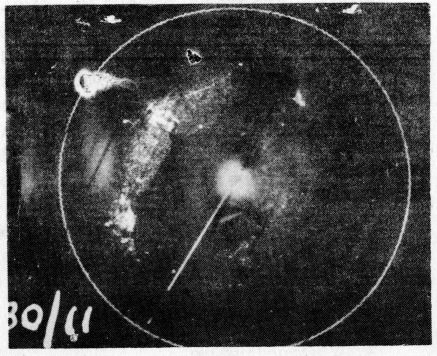 |
Figure 34a. |
Figure 34b. |
H2S Mk IV PPI photograph of a Convoy in Milford Haven (Height of aircraft 18,000 ft.) |
|
A larger number of flights were made with the experimental units to test the accuracy of wind finding The average of all the measurements made gives a figure of approximately 12 m.p.h. for the vector error; it is expected that this figure will be improved with the prototype units, since on these the accuracy of the hyperbolic scan waveform is considerably better than that of the earlier units.
It is expected that a PFF fitment of Mark IV H2S will commence in the spring of 1945.