1. INTRODUCTION
H2S MARK VI
1. Introduction
H2S Mark IV described above, is a system in which the technique of accurate navigation and blind bombing has been considerably advanced over the earlier X band systems such as Mark IIIA, but the definition of the PPI picture has not been significantly improved. Mark VI, on the other hand, is an H2S system on K band, in which effort has been expended to make the best possible use of the increased definition available, while leaving the bombing and computing arrangements much the same as in Mark IIIA. It is, of course, extremely desirable to combine an advanced computing and bombing technique with the increased definition as soon as possible, and a system known as H2S Mark VII (originally called Lion Tamer) is under development with this aim in view. The reason for the interim Mark VI system is two-fold:-
It should be emphasised, however, that H2S Mark VI is an experimental system and present plans are to equip only one squadron of Lancasters and a few Mosquitos for PFF.
2. General Description of the Mark VI Equipment
In order to minimise the development and production time, the policy has been to make use, as far as possible, of units already in existence for other programmes, particularly from the earlier H2S systems. To this end the layout and functions of essential controls on units which are at the moment in the Service have been retained as
closely as possible on those of Mark VI. To a small extent bombing accuracy may be impaired by this, but on the other hand there is the advantage that the extra training required by operators is kept down to a minimum. Thus the Modulator is a modified Type 64, one Power Unit is one that is developed for ASV Mark VIB, the Waveform Generator and Switch Unit are modifications of existing ones while two Control Units are identical with those used on Mark IIIA. A Power Unit and Control Unit have had to be developed to meet the special requirements of the American R.F. head. The Indicator is a new unit and is being made common to another installation.
(i) The R.F. System
Up to the time when the Mark VI programme was first considered little or no work had been done in this country on the design of a K-band R.F. head, and it was therefore realised that any short term British K-band project would be entirely dependent on the supply from America of sufficient heads. This supply was promised and at the moment heads are being shipped to this country. A brief description of the unit is as follows:- it contains, the transmitter and its modulation transformer, TR and anti-TR cells, crystal mixers, local oscillator and A.F.C. circuits and power supplies for these latter. In addition, as distinct from previous heads, it contains all the I.F. amplification stages, one video stage and a cathode follower output feeding a signal of 1½ volts to the Indicator. The whole unit is pressurized (sealed at ground pressure) for operating at high altitudes with provision for maintaining that pressure by means of a barometrically controlled electric pump.
The magnetron oscillator is known as the E5A, (the Rising Sun magnetron,) with a direct waveguide output delivering a peak power output of between 35 and 45 kilowatts at fixed frequencies in the K-band with an internal magnetic field in the region of 5,000 gauss. On Mark VI it is pulsed at a repetition rate of 2,000 cps with a 1/4 µsec pulse; the duty cycle is thus 0.0005. It will however operate satisfactorily for duty cycles up to 0.0012 and for pulse width down to 1/10 µsec. The efficiency of the valve is in the region of 20%.
The local oscillator is called the QK33 and is the American version of the British Oxford tube VX302. A.F.C. circuits control the oscillator frequency, while at the same time provision is made for remote manual tuning. The I.F. frequency is 70 Mc/s and the bandwidth 12½ Mc/s to 3 db points, accomplished in 9 staggered single tuned stages with an overall voltage gain of 100 db. The video response is substantially flat to 10 Mc/s, providing a maximum voltage output of 1½ volts, corresponding to a power of 13.3 milliwatts. An external gain control varies the bias of the second and third I.F. stages. The receiver noise factor is approximately 6½ db.
Details of the K-band scanner are given in the article on the H2S aerial problem. The beam width for the 3 ft flat cheese scanner is ± 0.75° for half amplitude and the scanning system is roll stabilised over ± 30°. A 6 ft scanner is also under consideration, with a beam width of ± 0.30° for half amplitude. This is only just commencing its flying trials however and the Mark 6 programme will definitely be initiated using the smaller scanner. These scanners will be provided with a 3 position remote tilt control as in the case of the Mark III scanner.
(ii) The Display
Having increased the resolution of the system on the R.F. side it is essential that it should not be impaired in the method of presentation. While the electrostatically deflected CRTs with 4 kV anode/cathode volts gave a spot size which did not to any great extent impair the picture grain on S or X-band, it was agreed that it was not good enough for a K-band picture. Accordingly on Mark VI it has been replaced by a high beam current electromagnetically deflected CRT with 7 kV anode/cathode potential. The combination of high beam current, small spot size and sector display, mentioned later, allows full use to be made of the high resolution properties of the RF equipment.
Thus instead of having to provide voltage waveforms in quadrature to the deflecting plates of an electrostatic CRT to derive a rotating time base, it is now necessary to pass current waveforms through a magslip resolver and apply these
to the scanning coils of the magnetic tube. For the case
of a linear scan this problem provides no particular difficulty. But since the distorted ground range presentation resulting from a linear PPI scan will obviously spoil the inherent high resolution feature of the system, it is necessary to generate the hyperbolic scan waveform required for complete height correction of the picture, as described earlier in this journal, and pass this through the
magslip and scanning coils. This is more of a problem, or rather was, due to the difficulty in passing steeply rising waveforms through coils of the type available at the time. A method of doing this was not fully worked out at the beginning of the Mark VI development, and so, as an interim measure to allow the system to get going, a partially height-corrected presentation was designed by using a sinusoidal scan waveform controlled in amplitude and phase by the setting of the height-marker, the method of setting this being the
same as on Marks II and III. The amplitude of the sine wave
is thereby changed in proportion to height so as to make the slope of the scan approximate to the mean slope of an ideal height corrected scan; in this way the scale of the display
is kept constant for all heights. The phase of the scan relative to the transmitter synchronising pulse is varied with height in such a way that the zero of the sine wave scan
occurs first before the reception of ground returns. The
zero of the sine wave scan and the first ground return are made coincident at zero height and the delay between the scan zero and the height returns increases to a maximum of 10 µsec
at a height of 25,000 ft. This delay, although producing a hole in the centre of the picture, results, in combination with the sine wave amplitude variation, in a close approximation to a height corrected scan from maximum range into a range well within the bomb release point. This sine wave scan is displayed on an 8 nautical mile range scale; a longer range scan of 20 nautical miles is also provided which can reasonably be linear, since this range display is used principally for navigation, when the presence of distortion is of less consequence, and not for purposes of target identification and bombing.
A new H2S display feature, designed to increase bombing accuracy, is introduced in the form of a sector display obtained by switching the pivot point of the time base to any one of eight compass points round the edge of the tube, at the same time doubling the amplitude of scan so that the full diameter of the tube is utilised. This sector display is made available on both the 8 and 20 mile ranges; it will be used mainly on the 8 mile range on the final stage of a bombing run to give a clearer picture of the aiming point.
In other respects the display on Mark VI resembles that on Mark IIC and Mark IIIA except that scan ranges of more than 20 miles are not provided, in the first place because it was not anticipated that with the power likely to be available longer ranges would in fact be obtained, and secondly because there was no requirement, as on the earlier equipments, for beacon presentation necessitating a 100 mile display. North heading of the picture is arranged as before, the selection of course and track markers is available, the latter being derived from the drift angle information given by the Mark XIV Bombsight Computer. Variable height and range markers are displayed, the height-range triangle solving being done as before on the drum of a modified Switch Unit. The 30 sec. delay arrangement is omitted since the scanner polar diagram will allow the target to be seen into bombing range. Provision is made for feeding in external shift for the purpose of picture stabilisation, should it be desired on Mark VI from a GPI system such as is being designed for the improved Mark VII K-band equipment.
Referring back to the subject of height distortion correction, it was stated that the sine wave scan waveform was an interim measure only. A method of applying the fully corrected waveform to a magnetic tube has been evolved which will supersede the previous system at an early date on the production run of the units involved. This employs the self-correcting circuits developed for Mark IV where a network stores up energy during the time between the transmitter pulse and the reception of the first ground return and then gives it up as a correction which is added to a linear scan to give a fully height corrected PPI time base. This distorted scan waveform is automatically balanced by a further half cycle of equal area so that it can readily pass through the A.C. coupled circuits of an improved magslip and deflector coil system without losing its proper pivot point. This system involves a new low impedance magslip for which, until production of it has begun, the present type of magslip with matching transformers at both ends of the line can be substituted.
3. Conclusion
Such in general terms is H2S Mark VI. in summarising the present position it can be said that the system looks promising and that any doubt originally entertained as to whether there would be enough power on this wavelength to make the equipment meet navigational requirements has been dispelled. Flight trials in this country of an experimental set of units have resulted in ranges of 19 nautical miles at 15,000 ft., while in America, with a later and more efficient design of R.F. head, coast-line pictures have been seen at
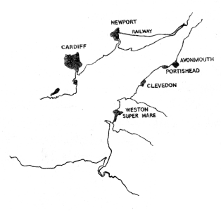
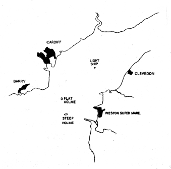
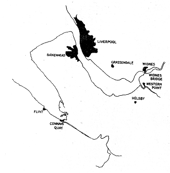
20 miles at a height of 24,000 ft. The picture definition is convincing. The evidence here at the present time, at least in this country, is confined to pictures of coastlines, rivers and open spaces such as parks; a study is being made of the appearance of towns and built-up areas and of the correlation of the H2S picture with the structure of the town. Examples of results are shown in Figs. 35a and b, 36a and b and 37a and b. Figure 35b shows Cardiff and Newport clearly with railway lines running into Newport. Figure 36b shows the excellence of the coast line painting and Figure 37b the potentialities of K band in a neighbourhood such as Merseyside.
 |
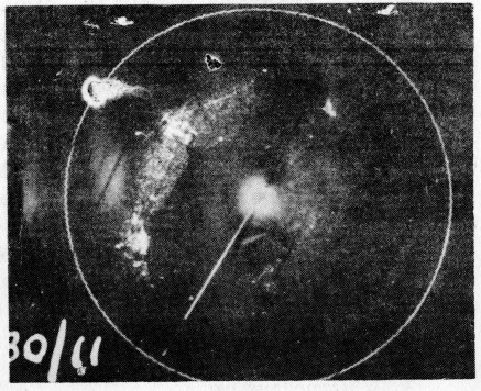 |
Figure 35a. |
Figure 35b. |
 |
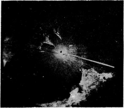 |
Figure 36a. |
Figure 36b. |
 |
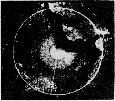 |
Figure 36a. |
Figure 36b. |
All the problems associated with the new technique of K-band have not been solved however. To mention only two basic ones, scanner design, especially from the production point of view, while it has progressed to the stage where a first design can be frozen, has still some way to go. Then again absorption by cloud is much more pronounced on this wavelength than on X-band; heavy rain clouds have been found to shield the ground considerably. The extent to which this effect is going to limit the operational use of the equipment is a question which, when more evidence is obtained, must be faced. A lot of effort however is being devoted to these and other problems both on the bench and in the air and there is reason to be hopeful.
It is anticipated that early in 1945 the equipment will be fitted in small numbers of Lancasters and Mosquitos for operational use.
Page last updated on 15th February 2018 by Colin Hinson