1. SUMMARY
These devices combine radar sighting on K and X wavebands respectively with
computing systems to provide general navigation over many hundreds of miles,
followed by bombing from 6,000 up to 35,000 ft. with an error not exceeding a few
hundred feet.
The fundamental idea which originated these equipments was that the three divisions, radar sighting, navigation computing and bombing computing, should have a unified design so that all data should be readily interchangeable from unit to unit (for instance, air speed and ground speed as voltage levels common throughout the equipment). This interchange was then made automatic instead of being affected manually or verbally as in the, past and the next step, to introduce computers for automatic dead reckoning and bomb release, became possible. By this rational design, and also because new techniques, such as in computing had reached maturity, substantial advances were made over previous equipments: (a) to increase markedly the accuracy of bombing and navigation, (b) to reduce considerably the demands on skill and attention of the crew.
A deliberate effort was made to preserve the independence of the three divisions of the equipment in fair degree so that breakdown of one part would not be catastrophic.
An important principle guiding the design was that the accuracy of navigation and the bombing attainable with these devices should ensure that, even if all lattice and beacon navigational aids were unusable, an economical bombing policy could be pursued, For this purpose, navigation had to be accurate enough to utilise the tactics of extreme concentration which have served us so well in this war, while, for the necessary high accuracy in bombing, a reference point facility was provided so that a clear cut radar echo in the neighbourhood of and at a known distance from the desired target, could be used to define the release point with precision. At the same time, a generous latitude on airspeed, weaving, climbing, or diving and of direction of approach was to be permitted to the pilot.
Finally, the need for an equipment capable of being installed in the fast small bomber and the special need of a very long range heavy bomber for radar guidance for the last 60 to 100 miles of a long sea trip necessitated the adoption or two types of equipment, H2S Mark VII and H2S Mark VIII respectively for these tasks.
The article concludes with a brief review of possible future developments for these radar sighted navigation and bombing devices including the use of superposed maps, two-wave transmitters and doppler navigation.
2. GENERAL CONSIDERATIONS
To describe with any degree of completeness equipments so
comprehensive in their functions as H2S Mark VII and VIII
would easily fill several TRE Journals, but there is a need
for an article which describes briefly why such equipments are
necessary, what they set out to do and how they do it, restricting to a minimum, discussion of the more technical points of
design. It is hoped to be able to deal with the latter more
fully in a future publication.
In considering whether radar sighted navigation and bombing devices such as H2S Marks VII and VIII are likely to remain useful and essential in face of possible countermeasures, it must be borne in mind that, although extensive jamming of radar devices is to be expected in future wars, H2S with its narrow moving beam relying solely for its information on reflection from the ground, is very difficult to jam; furthermore, the other possible countermeasure: homing, can be combatted by radiating for very short periods only. When H2S is being used for navigation, the fact that its aerial system is downward looking would call for too widespread a scattering of enemy effort for the device to be effectively jammed, while jamming at the target to prevent accurate bombing can be overcome by judicious choice of the line of approach and the use of reference point technique. Consequently, as long as non robot bombing is needed, it is considered that there will always be a requirement for H2S.
The history of radar in this war has been one of sudden inspiration, followed by a burning optimism and then, on each equipment, a painful period during which the earlier design, which had barely worked, needed to be cleared-bit by bit of the more outstanding faults. Thus in H2S, as a result of operational use and improvements in technique, modifications and additions were effected and these yielded a certain patchwork quality to the later Marks of H2S. The situation was, to some extent, relieved on H2S Mark IV, but this suffered from being designed to fit in with navigation and bombing aids which were already in existence and were not themselves suited to link up with H2S. Production-delays have also contributed to make this Mark unjustifiably out of date. It is now hoped that this phase of ad hoc modification has passed, and that an H2S set can be produced, using every development. in the way of brighter and finer CRT displays, miniaturisation, tropicalisation and improvements in serviceability and reliability, to meet all the needs of a Service aircraft for long range navigation and accurate bombing computing in addition to the facilities which the earlier Marks of H2S attempted to provide.
H2S Marks VII and VIII started with the advantage that the navigation and bombing computing divisions were designed along general lines to fit in with each other and with the radar sighting division. This meant establishing data in common forms, for instance, transforming air speeds and ground speeds into voltage levels, such that transfer of data from one into another of the divisions could readily occur without the intervention of manual or verbal actions. This enabled a large measure of automatic operation to be built into the equipment. This process-was extended by the development and adoption of integrating devices enabling ground speed to be changed to ground displacement.
It has long been felt both on visual bombing, as well as on radar sighted bombing that a system should be produced so that, however invisible the real target might be, a sighting on a neighbouring visible feature of a clear-cut nature at known bearing and distance from the real target, would result in highly accurate bombing. This means of improving accuracy has been adopted in the radar sighted navigation and bombing devices under discussion. Two possibilities are covered; in the first, a suitable. reference point is chosen on briefing, and, in the second, a correction can be rapidly introduced by the operator when the aircraft is in the target area so as to increase the accuracy of parachute flare marking and the dropping of "clusters" of ground markers.
Wind finding, as in the past, is essential in this equipment and is made very simple and accurate.
In order to give the pilot as much liberty of weaving during bombing as possible, he is provided with an instrument showing him his actual divergence between track and target bearing with markers which automatically show him his permissible weaving limits and the distance to go to the target. He has also a fair degree of freedom in climbing or diving, and in airspeed and his line of approach is not restricted by other than tactical considerations. The same pilot's direction indicator can be used to give direction and distance for any series of "hops" from one landfall or landmark to another on the outward or homeward journeys, the length of the "hops" being about 400 miles.
In the case of H2S Mark VIII, the X band equipment, the
fact that X band beacons are often installed at base has been
borne in mind and a long range is available (about 100 miles)
together with a suitable pulse for interrogation. This
supplements the 60 to 80 mile range on coast lines available
on that equipment.
Although the "K" band equipment, H2S Mark VII, lacks the long range coast line and beacon facilities of H2S Mark VIII which normally enable navigational inaccuracy over the long hops" to be discounted, the fact that the Mark VII equipment is intended for installation in the faster aircraft makes this omission of less account since the main cause of navigational inaccuracy, ignorance of wind, has proportionally less weight on such fast aircraft.
The policy of concentration of the aircraft has been proved to be one of the greatest importance for the reduction of aircraft losses. This concentration, has been effected mostly by arranging a G fix as a rendezvous and thereafter navigating along a G line. The resulting "gaggle" would have a front of 10 to 20 miles and a concentration of 2 or 3 aircraft per cubic mile. These tactics were very effective in requiring a minimum of target marking and in providing a maximum degree of saturation of the defences. It is likely that beacon or lattice systems may be inoperative in the future due to heavy jamming, but H2S Mark VII and VIII can readily achieve. this degree of accuracy in navigation.
The problem of how much duplication of facilities must be provided with any aircraft device so that the aircraft is not lost because of its failure is a very difficult one involving as it does the balancing of a definite increase in weight against an indefinite probability of loss if that weight were saved. In the Navigator's Panel, for instance, wind is displayed on N-S, E-W drums and in polar form on an instrument dial while airspeed is shown on another dial, and heading and track are displayed on still another. Although none of these indications are necessary when the navigation side of the equipment is working, they would be of great value if the navigation side failed and much more so if the radar side also broke down. Furthermore, by their aid, bombing could be effected by the radar and navigational sides of the equipment using a manual bombing computer even if the automatic bombing computor broke clown. For the sake of this small extra weight, a worth while degree of insurance is attained. A similar policy is pursued in the provision of power units and controls so that the three divisions, radar sighting, navigation and bombing computing are, to a great extent, independent. Although this clearly does not give as great security as the policy of complete duplication of radio equipment often adopted in civil aircraft, the danger consequent on failure is much lessened by all these measures.
It must be realised that many of the H2S features of these two equipments have been provided. in one form or another in earlier marks of H2S although generally in an immature state of development. Partly from this historical point of view and also to avoid labouring points already made in other published articles on H2S the following paragraphs should be noted.
3. LIST OF H2S MARK VII AND H2S MARK VIII FEATURES COMMON TO EARLIER MARKS OF H2S
4. LIST OF NEW FEATURES IN H2S MARK VII NOT OCCURRING IN EARLIER MARKS OF H2S
5. LIST OF NEW FEATURES IN H2S MARK VIII NOT OCCURRING IN EARLIER MARKS OF H2S
The remainder of the New Features on H2S Mark VIII are the same as items 3 to 13 in Section 4 above.
6. GENERAL PERFORMANCE
Although the performance of the equipment will be gathered in more detail from Section 9, it will be briefly summarised here. On the H2S Mark VII, the "K" band equipment, a relatively small scanner gives an azimuthal resolution of rather over 1 and should give a range of 15 - 20 miles at 20/25,000ft., the exact performance depending rather on the weather conditions.
In the case of H2S Mark VIII, the "X" band equipment, a 66" scanner gives slightly worse angular resolution compared with the Mark VII equipment, but the greater power on "X" band and the reduced attenuation due to atmospheric absorption enable coast lines to be picked up at ranges of 60/80 miles, so that, even after long sea journeys, navigational errors are unimportant since accurate location is easy.
The navigational accuracy depends very much upon the care taken in wind finding but it should be possible to achieve ¾° about in bearing and 1% in range in favourable circumstances. When the aircraft is flying over land or sea, lacking land marks or islands upon which wind finding can be accurately effected, it will be appreciated that any changes of weather front which may occur will result in considerably greater errors.
The accuracy of measurement of plan range and bearing to target depends on the resolution of the cathode ray tube displaying map and markers, the errors in the slant range computing system and the errors in the plan range triangle solver. On the shortest range, the spot size of the cathode ray tube would not give rise to errors.of more than about 60 feet and an approximately 120' error will occur in the slant range computing systems. On the plan range triangle solver the maximum error will be about 250 feet and in bearing for a typical case at 2 miles range.
The above, of course, comes into the assessment of bombing accuracies, but the major errors in this case are
(a) Errors in marker shifting, wind finding and instrument-guided flying due to normal human imperfection when operating at such heights as 20,000 to 35,000 feet.
(b) Errors in radar sighting of the point to be bombed due to lack of clear-cut features.
(c) Errors due to compass inaccuracies when an off-set or reference point is used for bombing.
In general, it is expected that bombing accuracy for direct bombing will be 20 to 25 mils, i.e., 400 to 500 feet radius of the 50% none for bombing at 200 knots from 20,000 feet, although it is likely that some improvement will be obtainable when possibilities of recompromising to eliminate some of the errors have been carefully investigated.
One of the most important points in this connection is the accuracy to be expected on offset bombing. A reasonable assumption is that the distance between true target and the reference point is about 30,000 feet. It is to be expected that even with the improved design of compass, compass errors which arise due to weaving,will be 1½° to 2° (probable) so that the error from the above spacing would be 900 feet. Taking a bombing height of 20,000 feet and with 500 feet for the normal direct bombing error, the overall probable error would be 1080 feet, i.e., 360 yards. A comparison considered to be fair between H2S Mark IV and Mark VII (and VIII) would be:-
Mark IV Mark VII (and VIII)
Direct Bombing 300 yds 170 yds
Reference Point Bombing 1000 yds 360 yds
although the 170 yard figure for Mark VII (or VIII) may quite possibly be improved upon.
When it is borne in mind that the difference between the 1000 yard and the 360 yard figures represents 8:1 difference in area, and that, for a small area such as an, oil refinery, 8 times the bombers would be required to saturate it using H2S Mark IV compared with the number required using Mark VII or VIII, the importance of striving for very high accuracy in bombing becomes really apparent. The small size of the residual error in bombing With H2S Mark VII and VIII is also emphasized if Figure 5, (Reference Point Bombing) be examined. The 360 yard radius is drawn here to show it in comparison with the built up area of a town such as Swansea.
7. CONTROL AND COMPUTATION
Before discussing engineering design points or features
of especial interest on individual units, a broad outline will
be given below of the mechanism of control and computation in
these devices. It will be helpful to refer to Figure 1, a
simplified schematic of the whole equipment which shows the
interconnection and interrelation of the main divisions and
the forms in which the data are stored at various points of
the equipment. For clarity, rotating shafts are shown as
continuous from one division of the equipment to another but
this does not, of course, occur in. practice; furthermore,
it must be remembered that, in general, motion is transmitted,
from one end of any shaft to the other and not vice versa.
Step up and step down gears are not shown; it may be borne
in mind, however, that frequently a change of range is simply
effected by gearing down a potentiometer and simultaneously
changing the scale of its output voltage.
 Figure 1.
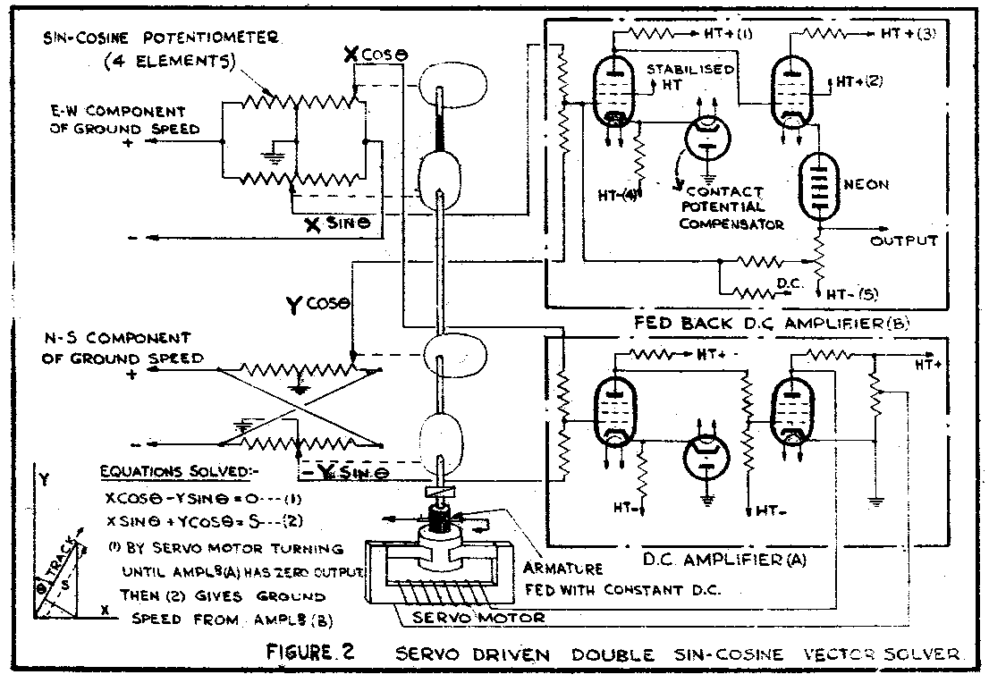 Figure 2.
The Air Mileage Unit. gives out true air speed as a voltage which is resolved into N.S. and E.W. components by a sine- cosine potentiometer driven by the gyro compass. To these voltages are added voltages representing the N.S. and E.W components of wind velocity, the sum representing the rectangular components of ground speed. By means of a double sine-cosine potentiometer servo-motor driven to solve the triangle involved -(see Figure 2), the rectangular components are changed to polar coordinates representing ground speed and track. Dealing now with the ground position computation, the two rectangular components of ground speed are separately integrated (see Figure 3) by producing shaft rotations proportional to the ground speed components and counting the revolutions to give the components of ground position departure.
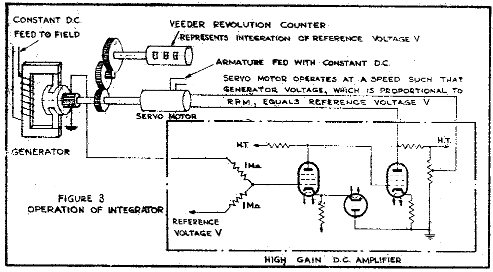
Figure 3.
In the actual equipment the results are expressed as latitude and longitude utilising, to derive the latter, a secant gear driven by the latitude shaft. These shafts which revolve according to N-S and E-W movement drive, when required, target marker shift potentiometers so that the marker has a motion corresponding to that of the aircraft and remains stationary in regard to any particular ground feature shown on the PPI map. Before dealing with target slant range and plan range computation, it may be mentioned that, besides stabilisation of the marker, when desired, the whole PPI picture also can be stabilised in a similar way on the C.R. tube screen so that ground features over a period of 5 to 10 minutes remain stationary on the screen face. The radar equipment inherently measures slant range from aircraft to target but, in wind finding and also in bombing computers used up to the present in this country, it is plan range of the target and its time derivative that is required. The transformation from slant range to plan range is effected by an electronic computer into which voltages are fed proportional to plan range and height, and a marker pip delayed after the transmitter pulse by a time corresponding to slant range results. This marker pip generates the range ring on the PPI. The electronic computer used is of considerable circuit ingenuity and works on the basic principle that the voltage on a condenser charged through a resistance from a rising saw tooth wave varies as the square of the charging time; whence it is clear that triangle solving is possible by suitably arranging times. of charge and discharge. In turn, plan range of the target is calculated from two voltages representing miles N-S and miles E-W stored on the manually controlled target marker shift potentiometers, a servo-operated double sine-cosine potentiometer being employed for solving the triangle in the same way as that used for ground speed. In the former case, the angle computed represents target hearing and in the latter case track. When bombing, the angular difference between these is fed to the Pilot's Indicating Unit and represents the amount of turn needed before bombs are dropped.
When wind-finding, the target marker is set on a clear cut feature and the wind-button s pressed. This allows each shift potentiometer to drive its appropriate wind storing potentiometer through a variable gear, the ratio of which is automatically increased linearly with time so that any shift needed to restore coincidence of marker and echo produces the appropriate change in stored value of the wind data.
The bombing computer relies on an empirical formula:-
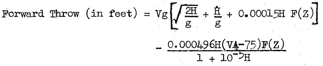
where the last term in the bracket represents the time delay
in the fall of the bomb compared with its Value in vacuo,
the succeeding term is the tangent of the angle of lag (λ) of
the bomb at the moment of impact viewed from the aircraft
and:-
Vg is ground-speed and Vh is air speed in feet per second.
H is aircraft height in feet and H its time derivative.
F(Z) is a function of the terminal velocity of the bomb, the value of which is derived from tabulated data.
g is the acceleration due to gravity.
To determine the point of release for bombing, the plan distance from aircraft to target has to equal the forward throw as calculated by the above formula. These quantities are transformed into voltages, plan distance being negative and all the above component terms of the forward throw except the last are positive, and are added together. The difference represents "distance to go" before bomb release and is displayed on the pilot's direction indicator where it also controls the "limits of weaving" indicators. When this "distance to go" becomes zero a relay normally energised drops back and the bombs are then released. (See Figure 4, The Bombing Problem).
Figure 4.
Two types of off-set bombing are provided:
The provision of off-set bombing facilities pre-set before taking off is relatively simple. The stabilised reference voltages normally fed across the N-S, E-W target marker shift potentiometers are simultaneously fed to two off-set shift potentiometers which are calibrated in miles N-S and miles E-W spacing between true target and reference point. The outputs from the target marker and off-set potentiometers are summed separately in N-S and E-W directions and the sums are applied to a servo-operated double sine-cosine potentiometer from which off-set range and bearing are derived. In practice the energisation of the potentiometers and amplifiers is from 400 cps A.C. and this is restored to D.C. for range marker ring generation for display on the PPI CRT in the normal way. When these markers are set to the off-set target echo by means of the normal X and Y target marker shift controls, the voltages then present on the potentiometers controlled by the latter define the position of the real target and, through the target sine-cosine potentiometers, the pilot's indicator is controlled and the release of the bombs effected in the manner described earlier. A typical exampled of this type of reference point bombing is shown in Fig.5.
 |
 |
Figure 5. |
The second type of off-setting is effected by setting the markers on the true target when the latter is some 5 miles or so away in plan position and then making additional adjustments of the target marker shift controls until off-sets are indicated on the vernier shift dials to correspond to calculated errors in the fall and drift of the flares or ground markers similar method is used for the correction of errors due to the cross trail of low T-V bombs.
ENGINEERING DESIGN
The purpose of this section is not to deal exhaustively
with details but to emphasize what is new in the engineering
design of the units comprising H2S Marks VII and VIII.
Reference should be made to Figure 6 which is a block
schematic showing these units, their stowage in the aircraft
and the auxiliary equipment needed to run the installation.
Approximate sizes and weights of the units are marked.
 Figure 6.
To ensure a high degree of resistance to tropical conditions the units are housed in completely sealed pressurized containers and furthermore, to guard against permanent deterioration when the case is opened up for servicing, the components used are tropically finished. This policy of using sealed containers would normally be cumbrous and weighty, but the situation is relieved by reducing the number of units to a very few and building each of these, where possible, in the form of multiple plug-in units to reduce the amount of external cabling, plugs and sockets. Almost all the main units are in cylindrical form of single ended construction. They are pressurized by dry air from a ring pipe line from a single pump on the scanner. Many of the units have stirring fans inside them to maintain an equable temperature over their containers and heavily loaded units are provided with a fan for cooling the outside. To facilitate cooling, the general shape tends to be long and thin.
Where the omnibus units are complicated either because they embrace a large number of different functions or because their circuits form a ring, i.e. feed pulse sequences from output into input again, (such units, in case of failure, are extremely difficult to fault-find), they are broken up into plug-in units inside the omnibus unit. These can readily be replaced one by one when a fault occurs so that the fault can be easily located and rectified. Plug-in units have also been adopted for sections of the circuit which are identical in Modulator Units Types 203 and 222 for H2S Mark VII and H2S Mark VIII respectively. These sections are designed as common plug-in units so simplifying servicing and the stocking of spares.
Considerable effort has been exerted to keep the size and weight of all units down to a minimum and in many places miniature valves are used. Miniature plugs and cables are employed throughout the units but the introduction of miniature components has not been possible on as large a scale as really desirable as the supply situation is not sufficiently easy.
In the radar side of these equipments, which is of more recent design than the navigation side, A.C. operation of the servo-amplifiers and range computer is used so that a very good degree of freedom from errors due to valve drift is attained. In the case of the navigation side, D.C. connected amplifiers are used with feedback to reduce the effect of valve changes.
In the past, radar equipment design has been seriously
complicated by the need to work off an engine driven aircraft
power supply whose frequency varied from 800 to 2,500 cps or
more and whose waveform was very poor. At an early stage in
the development of H2S Marks VII and VIII it was decided that
this type of power supply was undesirable and unnecessary.
Instead, a DC - AC converter giving a constant frequency of
1600 cps ±1% was developed which had good waveform and was
controlled to ± 1% in output voltage. This, among other
advantages, enabled the weight of the power supply components
to be reduced very considerably.
In striving after accuracy the desirability of improved gyrocompass performance and the necessity for scanner stabilisation had to be considered. The first was met by the installation of the GIII compass with its improved gyro-scope, the mounting of a robust "fluxgate" element out of harm's way in a wing-tip and the improved accuracy of repeating. Scanner stabilisation relies on servo operation controlled by a Central Stabiliser consisting of a high class gyroscope monitoring the attitude of the aircraft in roll and pitch. Where the installation does not include the Central Stabiliser, its functions must be met by providing Control Unit Type 512 instead. Both the GIII compass and the Central Stabilizer have been designed in close touch with the development of H2S Marks VII and VIII so that the needs of these equipments can be satisfied.
9. DETAILS OF THE UNITS FORMING H2S MARK VII AND H2S
MARK VIII
It will, be helpful to make reference again to the
functional diagram Figure 1 and to block schematic Figure 6
when reading this section, the aim of which is to show how
the various functions are allocated to different units and
to specify the units very briefly.
The navigation division of the equipment consists mainly of two units, the Computing Unit, containing servo and output amplifiers, and the Navigation Panel, which houses the servo motors, resolvers, velodynes, wind storing potentiometers and so on, together with a set of dials which displays to the navigator the instantaneous air speed and aircraft heading, wind speed and direction, ground speed, track and drift angle, together with ground position indicated directly as latitude and longitude. The wind finding mechanism is mainly housed in the Control Unit on the radar side and will be dealt with later.
From the navigation side and from the bombing computer, signals are derived which show on the Pilot's Indicating Unit, the error angle between target bearing and aircraft track with the distance to go to the bomb release point; in addition this instrument sets limits to the degree of weaving which the pilot may perform and still recover the correct track in a rate one turn so as to deliver the bombs in the correct direction. This Indicator is also used for long distance homing in conjunction with the radar Control Unit and this point will be discussed later.
There are 6 main radar units: Scanner (the latter incorporating R.F. head and certain items of computing mechanism as well as a central pressurizing unit) Modulating Unit, Control Unit Type 524, Indicating Unit Type 236 and Waveform Generator Type 48.
The main features of the Modulating Units and R.F. heads associated with H2S Mark VII and Mark VIII are listed below in Table I. Scanner properties are detailed in the succeeding Table II.
TABLE I
R.F. HEADS AND MODULATORS OF H2S MARK VII AND MARK VIII
H2S Mark VII |
H2S Mark VIII |
|
Wave Band Short Pulse Length Long Pulse Length Beacon Pulse Length |
K ¼ uSec 1 uSec Not used |
X ½ uSec 3½ uSec 2¼ uSec |
The R.F. Heads are of the "casserole" type taking a peak modulating input of about 250 kW. The R.F. Head is mounted on the moving platform of the roll and pitch stabilised scanner together with a magslip for taking off a scanning waveform for the PPI cathode ray tube, servo operated sine/cosine potentiometer for off-set and true target range and bearing and servo operated D.R. compass intake. Information on the attitude of the aircraft is derived from potentiometers on the Central Stabiliser and fed to amplifiers in the Waveform Generator Type 48 and thence to the roll and pitch servo motors on the scanner. On the scanner, all motors, magslips and so on are enclosed in pressurized cases.
TABLE II
SCANNER PROPERTIES ON H2S MARKS VII AND VIII
H2S Mark VII |
H2S Mark VIII |
|
Wave Band Reflector Aperture Type of feed Gain of Scanner (End of max. lobe) Azimuthal Angle to half amplitude Speed of continuous rotation Sector scan. Complete Cycle of 80° |
K 32" Cheese x1500 1.3° 13 and 40 rpm One second |
X 66". End fed slotted waveguide x900 1.5° 13 and 40 rpm Two seconds |
| Tilt (3 positions) | 7±1°; 11±1°; 15±1° | 3±1°; 11±1°; 13±1° |
Maximum angle covered by roll Stabilisation |
±30° |
±15° |
Maximum angle covered by pitch Stabilisation |
±10° |
±5° |
Peak angular velocity for roll Stabilisation |
10°/sec. |
10°/sec. |
Peak angular velocity for pitch Stabilisation |
3°/sec. |
3°/sec. |
Peak angular acceleration for roll Stabilisation |
6°/sec./sec. |
6°/sec./sec. |
Peak angular acceleration for pitch Stabilisation |
2°/sec./sec. |
2°/sec./sec. |
Apart. from the use of plug-in units and the fact that a hydrogen thyratron acts as a modulator, there are no special points on Modulating Units, details of which are given in Table I.
The nerve centre of the whole H2S Mark VII or Mark VIII equipment is the Control Unit Type 524, of which a drawing of the front panel is shown in Figure 7. This Control Unit provides all the switching which is necessary for the operation and control of the entire equipment and enables a choice of ten functions to be made. These functions are listed in Table. III.
Figure 7. Front Panel of Control Unit Type 524
| Switch position |
Function |
Markers shown on PPI. |
Pulse length |
Pulse recurrence rate |
Remarks |
Aerial Scan |
Aerial Tilt |
||||
H2S Mk VII |
H2S Mk VIII |
H2S Mk VII |
H2S Mk VIII |
H2S MK VII |
H2S Mk VIII |
25,000 ft. |
12,500 ft. |
||||
1 |
100 mile PPI range (Beacon) 400 mile homing |
Not Used | Not available |
2¼ μsec |
Not available |
400 |
X and Y shifts calibrated in miles for 1st fix to 2nd fix |
- |
13 rpm |
2 |
1 |
2 |
100 mile range (PPI) 400 mile homing |
Not Used | 1 μsec |
3½ μs |
600 |
250 |
X and Y shifts calibrated in miles for 1st fix to 2nd fix. H2S Mk VII operated on 25 mile range. |
13 |
13 rpm |
2 |
1 |
3 |
100 mile sector | Not Used | Not available |
3½ μs |
Not available |
250 |
- |
- |
13 rpm |
2 |
1 |
4 |
25 mile approx. PPI. | Track, course or north line. Range ring out to full scale. |
1 μsec |
½ μs |
600 |
1600 |
Picture matches 500,000:1 chart | 40 |
40 rpm |
2 |
2 |
5 |
Set | Not Used | 1 μsec |
½ μs |
600 |
1600 |
Leaves veeder counters of latitude and longditude free for re-setting | 40 |
40 rpm |
2 |
2 |
6 |
Take Fix (25 mile PPI) | Target azimuth and Range. Ring out to scale | 1 μsec |
½ μs |
600 |
1600 |
Target marker is run out to mark selected echo and inserts aircraft to echo distance on lat. long. counters | 40 |
40 rpm |
2 |
2 |
7 |
25 mile approx. Wind finding |
Target azimuth and Range Ring out to 25 miles | 1 μsec |
½ μs |
600 |
1600 |
Picture matches 250,000:1 chart Stabilised display. |
40 |
40 rpm |
3 |
2 |
8 |
10 mile approx. Wind finding |
Target azimuth and Range Ring out to 10 miles | ¼ μsec |
½ μs |
2400 |
1600 |
Picture matches 100,000:1 chart Stabilised display. |
Sector scan 1 cycle a second | Sector scan ½ cycle a second | 3 |
2 |
9 |
Bomb | Target azimuth and Range Ring out to 10 miles | ¼ μsec |
½ μs |
2400 |
1600 |
Picture matches 100,000:1 chart Stabilised display. |
Sector scan 1 cycle a second | Sector scan ½ cycle a second | 3 |
2 |
10 |
Reference point bombing | Offset target azimuth. Range ring out to 10 miles. | ¼ μsec |
½ μs |
2400 |
1600 |
Picture matches 100,000:1 chart Stabilised display. |
Sector scan 1 cycle a second | Sector scan ½ cycle a second | 3 |
2 |
NOTE:- On positions 7 and 8, the markers are placed on the target and then the wind button is pressed. This starts a 2-1 minute run during which successive target marker shifts automatically correct the stored wind Information.
In addition, control of the tuning of the R.F. oscillator in the R.F. head is effected from this unit and gain control on the L F. amplifier, the latter also being located in the R.F. head. As will be discussed later, the height of the aircraft is determined by an aneroid barometer located in the Bombing Computer and to correct this for changes of weather front, a height correcting control is located in this Control Unit. This enables a height marker to be set on the ground returns displayed on the height cathode ray tube in Indicating Unit Type 236 and automatically corrects the setting of the Bombing Computer height shaft. Control Unit Type 524 houses two potentiometers from which are derived voltages which represent the distance of the aircraft from the point marked by the target markers on the cathode ray tube and these potentiometers are of great importance as they govern, in very large measure, the accuracy of wind finding, navigation and bomb release. Accordingly, a very fine motion is provided for manual control and a motor driven motion is provided for rapid coarse setting. To enable the 400 mile homing feature to be obtained, the positions of these potentiometers are accurately indicated on veeder counters in miles, so that when the aircraft is homing from one known fix to another, these potentiometers can represent the difference in co-ordinates between these fixes.
There is another function which can be performed on this unit that is helpful when marking by dropping flares or by ground markers. The effect of drift due to ground level winds must be allowed for. When these winds are known, the off-set to the dropping point to correct for them can be calculated and by pressing the "flare drift" button, after setting the target marker on the cathode ray tube to coincide with the true target, the flare drift off-set indicators are turned by the shift knobs from their normal zero setting to the calculated marks. This provides 'false' information to the Bombing Computer and to the Pilot's Indicator. By appropriate calculations these same marker shifts can be used to correct for cross trail on low T-V bombs. (See also Fig.4 The Bombing Problem). In this case the proposed procedure would be to calculate out the necessary offsets and insert these when the aircraft was about 5 miles from the true target. The pilot would then see from his Indicator that a slight turn would be required to correct the course to overcome cross trail error.
The very important function. of wind finding is carried
out on this unit and consists in re-setting the wind storing
potentiometers in the Navigator's Panel. This is done
automatically by a system of target marker shifting which
operates as follows. A well defined radar echo is chosen and
the markers are shifted accurately on to it. In this case the
markers, if the wind information were correct, would be
stabilised on the chosen echo through the computing system.
The wind finding button is then pressed and after 1½ to 2 minutes the marker is re-set on the target echo. This process
automatically corrects the majority of errors in wind information stored on the wind potentiometers. Any slight residual
error can be eliminated by a further re-setting of the target
markers during the period of 2 to 2½ minutes after the initial
pressing of the wind button. The shift knobs during this
process, in Addition to their normal function, are made to
operate the wind-storing potentiometers through variable gears
automatically driven to change their ratio linearly with time
so that these potentiometers are moved to the appropriate
extent to correct the error in stored wind data evidenced by
the shift of the target' markers off the target echo.
A further function of this Control Unit is to enable a land mark whose latitude and longitude is known, to be used to eliminate-errors which have accumulated due to slight errors in the:computing-system or due to false wind information. In this ease the function switch is turned to "set" and the veeder counters showing latitude and longitude on the Navigator's Panel are set to the latitude and longitude of the feature which has been recognised. The function switch is then turned to "Take Fix" and the Markers are run out accurately to indicate the feature in question. During this process the computing mechanism has taken care of the shift of aircraft position which has occurred in flight. On turning the function switch off the "Set" and "Take Fix" positions, the operation of eliminating errors has been completed and navigation proceeds based on location by this land mark.
Indicating Unit Type 236 incorporates a PPI cathode ray tube of the Magnetic deflection type with excellent focus and brightness and a bright sharply focussed miniature cathode ray 'tube (viewed by a special lens) for height measurement. The PPI display has adequate freedom from height distortion, the distortion at any point over most heights being less than 1000 ft. This does not affect map reading and, since electronic markers are used time related to the transmitter pulse, this error does not affect bombing. The markers are very free from hum and jitter and if the reasonable assumption be made that error due to finite marker width is 1/3 the line width, the probable error from this cause on an 8 mile scan is only about 60 feet. As the height tube has a very fast expanded scale, it is possible to indicate height to about the same accuracy although there will be slight additional errors in transforming this information in the bombing computer. The detailed treatment of the errors in various parts of the equipment is too involved to be discussed in the space available here.
One of the most complex units in the whole of H2S Mark VII
and Mark VIII is the remaining unit, the Waveform Generator
Type 48. It fulfills a very large number of functions:-
electronic slant range triangle solver, distorted scan waveform
generator, scan waveform voltage-current transformation, height
range and azimuth marker generation, D.R. compass servo
amplifier, off-set and true target range and bearing servo
amplifier and output amplifier, and roll and pitch servo
amplifiers. Many of these sections are interconnected and in
some cases outgoing signals are fed back to an earlier stage.
To make adjustment and servicing simple, it has been essential
to break up the main unit into small plug-in units which comprise3 to 6 valves. The whole-Unit has only two controls,
the X and Y off-set bombing potentiometers and these are preset
before flight so that this unit does not need to be adjusted
in the air, and can be stowed amidships.
The bombing computer used with H2S Marks VII and VIII has some very interesting features. It incorporates an aneroid barometer the moving plate of which changes the position of a light iron core affecting coils in an A.C. bridge circuit so as to servo-operate a follow-up drive in sympathy with pressure change. In this way, a shaft rotates in proportion to the height and moves potentiometer sliders so that voltages proportional to height are obtained. One of these voltages is passed to the radar side and, by checking its value through the position of a height marker based upon it, an adjustment can be made from Control Unit Type 524 to set the height shaft of the bombing computor correct. The height shaft has an electrical generator connected to it so that a measure of H, the time derivative of height is available for use in the bombing computation. A potentiometer setting proportional to Y H over the range 6000 to 35000 feet is obtained by a pin wheel gear. Preset potentiometers take care of the different T-V (terminal velocity) bombs which may be used.
10. POSSIBILITIES FOR FUTURE H2S DEVELOPMENT
Naturally progress can and will be made to simplify equipment,-to reduce weight and increase reliability, to
produce equipment requiring little or no adjustment and to
make fault-finding and servicing rapid and easy, but these
are matters of normal development and in this section rather
more fundamental possibilities are dealt with.
It is thought that the most important need of any future H2S equipment is increased accuracy in reference point bombing. The analysis in the section above entitled "General Performance" indicates that compass error caused through a period of weaving results in practically doubling the direct bombing error of 200 yards, i.e. increasing it to 360 yds. Clearly it is desirable to eliminate this compass error and since there are fundamental difficulties in the way of improvements in the compass itself when the latter is subjected to a period of weaving, an alternative scheme is needed. One such scheme would be to use two suitably situated reference points and eliminate the compass error by matching these two points on the FPI picture to two markers by feeding in a correction to the compass input. This would cut out the majority of the error in reference point bombing compared with direct bombing and could give very high accuracy. A further alternative, although on the same basic principle, would be to utilise direct optical super-position of a radar picture of the target area (previously obtained by a reconnaissance sortie) over the normal PPI picture on the C. R. tube screen. This has been tried and shows distinct promise. In assessing the accuracy obtainable by this method it may be borne in mind that the scheme can really correspond to using two or more reference points and by suitable choice of these reference points quite high accuracy can again be obtained.
The next most important point where improvement is needed, especially if the above problem of accurate reference point bombing has been solved, is that of improved resolution. Considering the typical case of beam width of 1 1/3°; at 6 miles, this is 800 ft. wide and compares very unfavourably with the distance- of 150 ft. corresponding to the pulse length of ¼ microsecond. For the ranges needed in high level bombing, a very short wave-length cannot be used because of atmospheric attenuation, but even a change to 2/3rds of the "K" band wave-length would be distinctly advantageous. Such a choice would, however, rule out long range pick up of coast lines, which is a very desirable feature of any radar equipment for long rage aircraft. To meet this need, the design of an installation having a second wavelength in addition to the very short one mentioned above, is being considered. A common modulator and scanner reflector is obviously possible and with care in design, many other parts of associated equipment can be common so that the additional weight and complexity need not necessarily be prohibitive.
One of the most likely causes of operational error as differentiated from instrumental error, is the need for wind finding in present systems of navigation and bombing. If the speed of the aircraft can be automatically determined by the radar system this need would disappear and improved accuracy and ease of operation would result. The use of doppler beats from the ground echoes can enable speed to be measured. Tests have shown that an ccuracy on track of ½° is obtainable by this means and it is thought than an accuracy of 1% or 2% in ground speed could readily be obtained. A system has been projected on "X" band which should enable complete automatic doppler navigation to be effected. The design utilises a normal radar system with a special scanner which could, however, also be used for producing a PPI picture in the normal way. As neither doppler navigation nor radar need operate the whole time, it appears very likely that the same equipment would be useable for both radar and for doppler navigation, a proportion of the time being allocated to each.
Other ideas are being considered such as the use of a two-coloure C.R. tube with suitable gain switching to paint "town" green, "country" orange and "water" black, but such developments are not of major importance. In considering all these developments, the questions which are of most importance are whether the development improves the equipment performance, at the same time reducing weight and increasing simplicity and reliability or whether the proposed advantages are bought at appreciable cost in increased weight and complexity. Developments in the latter category must be subjected to very careful scrutiny because additional complexity demands a higher standard of training of crew, greater likelihood of breakdown, increased difficulty of servicing, greater delay in manufacture, higher first cost and extra stocking of spare parts, possibly all over the world. This is a formidable catalogue of disadvantages of increased complexity. Consequently the key note of all further development is to strive after simplicity still maintaining all essential features for efficient operation.
Page last updated on 12th February 2018 by Colin Hinson.