Introduction
In the article "Oboe Mark I and. Mark IIF, Communication and Constant Ranging System" by A.J. Blanchard, the reader will have become acquainted with the early method of maintaining an aircraft at constant range from the Oboe "Cat" station. The purpose of this article is an attempt to explain how the bomb release point is determined by the "Mouse" station and how, in the cases of Oboe Marks II and III, the same equipment may be employed to provide a more accurate method of tracking.
The Average Velocity Measuring or A.V.M. Mouse
Although this type of mouse is now seldom used, in the form of the electrical and mechanical mouse, it was the only type employed with Mark I and IIF stations. Since it has been superceded by the instantaneous velocity measuring or
mouse in the form of the automatic instrument employed by the Oboe Consoles Types 51, 52, 54 and 55, only its general principles will be discussed here.
For timing purposes the A.V.M. mouse produced six equally spaced half-microsecond pulses which could be applied to the magnified time base as black-out modulation pulses. They were adjustable in phase and position, and so, if the region round the target was strobed, then these blackout pips could lie in any desired manner in the target area, on the magnified time base.
In actual practice the leading edge of the sixth pulse-was set at the target range, and depending on the operational conditions under which the station was to be employed, the other pips were spaced between 0.5 and 1 mile apart.
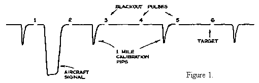
Imagine the aircraft pulse shown in Figure 1 to be moving from left to right across the magnified time base. If we measured the time the echo takes to move uniformly from the leading edge of pulse 2 to the leading edge of pulse 4, then we can predict the exact instant the aircraft signal would reach the target at pulse 6 provided the speed at which it moves across the time base did not change. Thus if at time t2 the signal was coincident with pulse 2 and at time t4 is was coincident with pulse 4 then it would reach the target at time t4 + (t4 - t2).
We are not interested in the time the aircraft reaches the target but in the tine T seconds before where T is the time of fall of the bombs, and this is the instant when the mouse must send out the release signal to the aircraft.
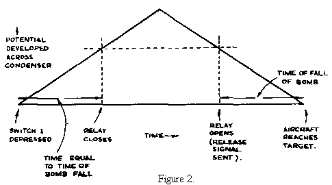
Let us now see how the electrical instrument predicts this instant of bomb release. When the aircraft signal passes pulse 2, a switch is pressed causing a condenser to charge - linearly in the manner shown by Fig. 2. After a time of T seconds (equal to the time of Figure 2. fall of the bomb) the potential reached by the condenser causes a relay to close. The condenser still increases its potential until the signal is coincident with pulse 4 when a second switch is depressed causing the condenser to discharge at the same rate as it was charged. When the potential, at which the relay closed, is reached, the relay now opens, sending a bomb release signal to the aircraft. By examination of Fig.2 it will be seen that this signal is sent out T seconds before the aircraft reaches the target.
Not always, however, were the charging and discharging rates of the condenser equal. Often the rate of charging was one and a half times the rate of discharge, and in this case, the measurement of the velocity was made between pulses 1 and. 3.
The A.V.M. mechanical mouse was identical to the electrical mouse in principle, but instead of utilising the potential of a condenser as its measure of time, it utilised the rotations of a uniselector.
The Advantages and Disadvantages of the A.V.M. Mouse
Simplicity, both in maintenance and setting up was a notable feature of the A.V.M. mouse. Although it could only be operated when the signal was preset at the time when switches 1 and 2 had to be pressed, its accuracy depended on a constant signal to noise ratio. Fluctuations in the signal to noise ratio caused phase shifts on the front edge of the aircraft signal and hence switches 1 and 2 were liable to be pressed at an incorrect time. Unfortunately a strobed AVC system such as is used on Oboe Mark II and III consoles could not be employed with the same ease.
The electrical mouse suffered from the non linear charge and discharge of the condenser though this non linearity did not of course, occur with the mechanical type. But the A.V.M. mouse was, unfortunately, not automatic, for personal errors due to the early or tardy depression of the two switches must always have been present to a greater or smaller degree.
Since it was considered that meteorological winds at an altitude of 30,000' were unlikely to remain absolutely constant in velocity for the duration of the bombing run, it was thought that inaccuracies in bombing were caused by using an A.V.M. mouse under conditions of varying mind speeds. Hence the operational requirement for the mouse arose.
The Instantaneous Velocity Measuring or I.V.M. Mouse
When the designs of the Oboe consoles, types 51 and 52, were under review, it was considered that a new type of mouse should be employed.
Such a mouse was designed to:‑
(a) be entirely automatic in its measurement of the tube velocity of the aircraft and its determination of the point of bomb release;
(b) be capable of being utilised for runs of the aircraft in both directions without having to be adjusted; (This facility was not, however, utilised under operational conditions).
(c) replace the old "Double Strobe" circuit for tracking; and
(d) be capable of producing a Delta track.
The Active Region and the Method of Setting up the Target Range
In Oboe operations, knowledge of the tube speed of the aircraft and its distance from the target (both measured in terms of volts) is only necessary over a small region around the target. This region is known at Mark II and III stations as the active region and is characterised by the appearance of
a 1¼ microsecond bright-in and a 1 microsecond black-out on the magnified time base. The former is a walking strobe and the latter, the target marker, is, in effect, only a type of CRT cursor.
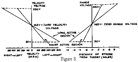
The position of the walking strobe may be controlled, either manually or automatically by means of an anode voltage known as the "Range Volts". This voltage is produced at the anode of the range tube and a change from a potential level of 50 volts to one of 280 volts causes the walking strobe to move 16 miles when the "Long Active Region" is employed or 8 miles when the "Short Active Region" is used. (Two lengths of active region are used to provide the utmost accuracy under all types of operational conditions).
If we choose a range voltage of 165 volts, the walking strobe will be the centre of the active region and so we define this voltage as the "Zero Range Voltage". This is the voltage that must be produced when the aircraft pulse is at target range. Hence before we attempt to set up the mouse, the range voltage must first be preset to a value of 165 volts.
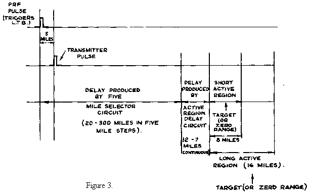
Two circuits are provided on the console to enable the active region to be set up correctly. The first is the "Five Mile Selector" circuit which enables the region to be set up to the nearest five mile pip; the second, "The Active Region Delay Circuit" provides a continuous adjustment of 2 to 8 miles. Thus having fixed the range volts to a value of 165 volts, the centre of the walking strobe may now be set to the target range, and the total swing of the anode potential of the range tube will cause the strobe to move four miles each side of the target for the short active region and eight miles each side for the long active region.
Facilities are provided on the console for viewing the whole of the active region on a slow magnified time base or any part of it on faster time bases.
The I.V.M. Mouse Circuit
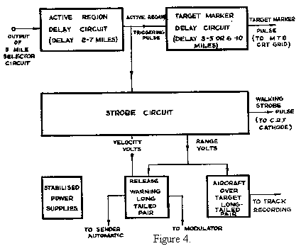
Fig.4 shows a functional block schematic diagram of the mouse circuit and from this figure it will be seen that the instrument consists of six units, viz:‑
(1) The Active Region Delay Circuit.
(2) The Target Marker Delay Circuit
(3) The Strobe Circuit
(4) The Release Warning Long-Tailed-Pair Circuit
(5) The Aircraft-Over-Target Long-Tailed-Pair Circuit
(6) The Stabilised Power Supply Unit.
Stated briefly, the function of these units are as follows:‑
The
Active Region Delay Circuit enables the active region to be set at the correct target range as previously described, whilst the Target Marker Delay Circuit enables the target marker to be adjusted to indicate the position of the target. The Strobe Circuit is really the heart of the instrument, for it is this unit which produces voltages proportional to the velocity of the aircraft and its distance from the target, enabling the Release Long-Tailed-Pair Circuit to compute the release point. It is in effect an "acceleration" strobe, the relative acceleration of the strobe to the signal being integrated to produce the velocity voltage. This velocity voltage is in turn integrated to produce the range voltage which in turn linearly controls the position of the walking strobe on the magnified time base, thus securing the locking of the walking strobe and echo. Since the strobe circuit is of the acceleration type, the phasing of the strobe and echo, when locked, does not vary with velocity, but only on the acceleration or deceleration of the aircraft echo as it moves across the tube. The Aircraft-Over-Target Long-Tailed-Pair circuit gives an indication when the aircraft is at target range as its name implies and though it has no direct operational use, it is used for the calibration of the Time of Bomb Fall control and for monitoring the flight of the aircraft during the use of the equipment in the cat station. The Stabilised Power Supply Unit generates the highly
stabilised voltage supplies necessary in an instrument of this precision.
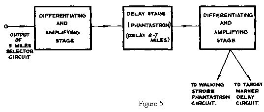
The Active Region Delay Circuit
This unit, comprises
of three stages. Its function is to initiate the active region at any range lying between 2 and 7 miles after the correct five mile pip chosen by the five mile selector circuit.
The delay produced by the circuit is obtained by a conventional phantastron circuit whose
length of screen waveform may be varied by adjustment
of the cathode potential
of the anode catching diode, and which is self-compensating as regards H.T. line variations.
The pulse produced at the output stage of the circuit performs two functions, (a) to trigger off the target marker delay circuit and (b) to trigger the walking strobe phantastron of the strobe unit.
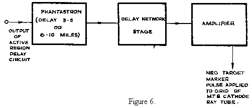
The Target Marker
Delay Circuit
This circuit
was designed to produce a 1 microsecond negative pulse at its output stage which could be varied in phase and which could be applied to the magnified time base as a blackout pulse.
The triggering input pulse to the unit is coincident with the start of the active region. The phantastron which it triggers must therefore have a delay of 3 to 5 miles for the short active region and a delay of 6 to 10 miles for the long active region so that the blackout may be set up anywhere within a mile or so of the target.
The delay must be adjusted by changing the voltage of the end of the phantastron grid leak and the value of the grid leak is changed when the length of the active region is changed. The phantastron is self-compensating as regards H.T. variations since positive and negative H.T. lines are used and the potentials of the cathode of the anode catching diode and the end of the grid leak are derived from the same stabilised source.
The 1 microsecond target marker pulse is produced by means of a delay network in the anode circuit of a valve on whose grid is applied the screen waveform of the phantastron. The positive pulse produced coincident with the back edge of the phantastron waveform brings the grid voltage of the output stage above its cut off potential and therefore produces a negative pulse at the anode of the valve.
The Strobe Circuit
Since a comprehensive description of this unit is beyond the scope of this article, only the general principles will be outlined below.
The output of the active region delay circuit is fed into the walking strobe stages as indicated in Fig.7. These stages produce the double walking strobe whose phasing or position bears a strictly linear relationship to the range voltage which may be controlled either manually or automatically by the range tube. One of the strobes is fed to the magnified time base as a bright-in, whereas both are fed into the co incident stages of the unit.
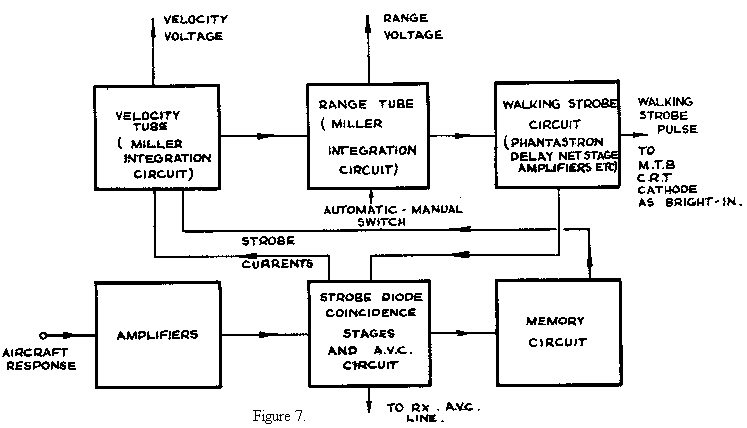
Let us assume a signal is present on the active region. This is fed to the coincident stages via amplifiers and now let us adjust the range voltage by means of the manual controls on the instrument so that the strobes overlap the aircraft signal. Strobe currents are immediately produced which are fed into the grid of the velocity tube, causing its anode voltage to fluctuate. But the, anode voltage of this stage is integrated by the range tube, if the "Auto Manual" switch is turned back to the "Auto" position. Thus the fluctuation of the anode voltage of the velocity tube will cause a phase shift of the walking strobe which will continue until the aircraft signal and strobes are correctly locked. When this occurs the residual strobe current fed into the grid of the velocity tube will be zero, and on account of the nature of the circuit, the anode voltage will remain constant so long as the tube speed of the aircraft remains constant.
It may be doubted if the anode voltage of the velocity tube is a true measure of the velocity of the aircraft but if we assume that the range tube is a perfect integrator and that the delay of the walking strobe stages is strictly proportional to the range voltage, then the anode voltage of the velocity tube must be a true measure of the tube speed of the aircraft. (The finite gain of the range tube and the leakage resistance of the feed-back condenser employed in its circuit prevent the stage from being a perfect integrator but the corrections which may be applied are of a very small order).
The memory circuit associated with the coincident and velocity tube stages is a useful feature incorporated to enable the instrument to memorise the last measured velocity of the aircraft should the signal fade. This facility enables the strobe to be in correct locking position should the aircraft signal return, or should it fail to re-appear on the tube, the time of the bomb release signal can still be predicted. The strobing circuits are also used to provide a strobed AVC system which reduces errors due to the phase shifts and width changes of the signal which occur when the amplitude of the signal varies.
When the length,of the active region is changed, the grid leak of the phantastron in the walking strobe circuit is altered in value and this either halves or doubles the sensitivity of both the range and velocity voltages. (See Fig.8).
It should be noted that, whether the equipment is being utilised in the mouse or cat stations the strobe circuit works in exactly the same manner. When the aircraft has settled on the circular track, however, the tube speed of the aircraft is fluctuating about zero (i.e. the velocity voltage is approximately equal to 165 volts).
The Release Warning Long-Tailed-Pair Circuit
This unit is really the predictor of the mouse for its
stages utilise the information relating to the tube velocity and position of the aircraft in determining the instant when the bomb release signal is to be sent to the aircraft.
It is, in effect, a kind of electrical balance with the range voltage fed in on the one pan and the velocity voltage fed in on the other. The point of balance is adjusted by means of the time of bomb fall potentiometer which adjusts the proportion of velocity voltage fed into one pan, and when the circuit in 'balanced" a relay in the anode circuit operates, sending the release signal to the aircraft. Without delving into the mathematics of the stages, let us see what happens when an aircraft moves from left to right across the magnified time base (i.e. with a positive velocity).
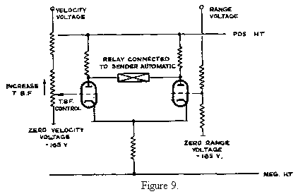
In this case the velocity voltage will be less than 165 volts and therefore the long-tailed pair will only balance when the range volts are less than 165 volts.
That is, the bomb release warning will be sent out before the aircraft reaches the target as must obviously be the case. If the T.F.B. control is now adjusted so that a larger proportion of the velocity voltage is fed into the circuit, then the point of bomb release will be reached earlier.
In circular tracking, the depth of modulation depends only on the position of the aircraft with respect to the target. Thus if we fix the velocity voltage to that corresponding to that of zero velocity or range, the direction of the current flowing through the relay depends on the range volts. In other words, the value of the range volts determines which of the two valves in the electrical balance is conducting more highly than the other.
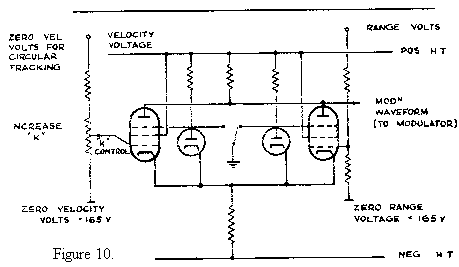
Thus if we modify the circuit as shown in Fig.10, with the facility of cutting off the flew of current through the two valves alternately with a 3½:1 on-off ratio the amplitude of the waveform produced at the common anodes depends on the value of the difference between the value of the ,range volts and 165 volts and the sign of the waveform (i.e. whether it is a dot or dash waveform) depends on whether the range volts are less or greater than 165 volts, This waveform is fed to the modulator to provide the width modulation of the system.
The circuit is perfectly suited also for the Delta system (i.e. exponential catting) since a voltage proportional to the tube speed of the aircraft is fed into the unit. The value of k in the formula r + kr = 0 is preset on the T.F.B. control since k is effectively the T.B.F. Just as in the case of mousing when the release signal is sent to the aircraft before the target is reached, so also is zero modulation sent to the aircraft before the circular track is met.
The Aircraft-Over-Target Long-Tailed-Pair Circuit
This unit is almost identical with the release warning long-tailed-pair when used for mousing, only that, instead of feeding in the velocity voltage, a voltage equal to zero range voltage is fed into one grid. Thus the relay in the unit only de-energises when the walking strobe is at zero range.
It serves no direct operational purpose, but when the T.B.F. control is being calibrated, measurements of the time between the operation of the release warning and the aircraft-over-target relays are made. During cat operations a recording milliammeter takes the place of the relay giving a complete track record of the flight.
Relative Merits of A.V.M. and I.V.M. Mice in the Presence
of Flying Errors
Since no pilot can fly his aircraft along a dot-dash beam (especially a circular one such as that employed by Oboe) without weaving, it will be appreciated that a considerable bombing error is due to this effect.
The interested reader should consult the A.W.A. Report No. 58, "A Comparison of the Extent to which Flying Errors Vitiate the Performance of Various Mousing Systems" by C. Brook and W.R.B. Hynd. Mathematical considerations have brought its authors to the following conclusions:‑
It should be borne in mind that this report was written before the operational use of the Delta system and the stated value of 60° for the critical angle of cut is likely to be quite erroneous for several reasons. The report, although realising the existence of wind fluctuations during the Oboe bombing runs assumes the wind to be constant. Up to the present no experiments have been made to disqualify this assumption, but trials are to be conducted at a pair of Oboe ground stations to measure from second to second wind changes at an altitude of 30,000'. Bombing trials carried out at West Freugh, in Wigtownshire, with an angle of cut of 22½° indicated that, using the Delta system, the results are considerably better than the A.W.A, report could predict, and would compare favourably with the accuracy of Oboe operations with angles of cut of 50 - 60° using the non Delta tracking.
The Delta System
In an effort to improve Oboe accuracy, an attempt was made to improve the beam flying of the aircraft. For this purpose the Delta system was utilised in which the modulation heard by the pilot depended not only on his lateral distance off track but also on his speed at right angles to the track. Thus the pilot could hear zero modulation when he was not on the circular track but on an exponential approach to it. The principles of this system are discussed below in the article Delta Oboe by A.M. Uttley.
The system has two main advantages, namely:‑
(a) It affords a very much easier approach to the circular track.
(b) It-improves the beam flying.
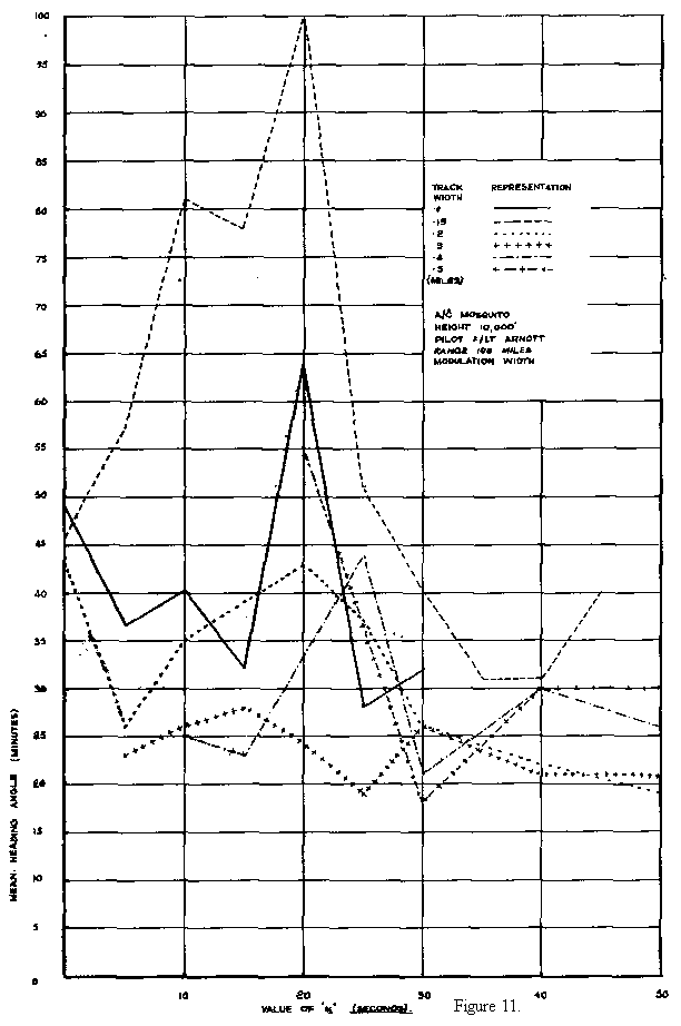
Experiments were conducted using a single Oboe Cat station and a Mosquito aircraft, and track records of the flying performances of the pilots were made using different track widths and different values of k, the rate aiding time constant.
The 'badness" of the flying was measured in terms of the mean heading angle, θ, and with a track of 0.2 miles and a k of 40 seconds the value of θ appeared to be less than half the normal operational value. The average angle of weave found from an analysis of a number of delta tracks was 0° 22'. highly than the other.