In the Oboe system, communication from the ground stations to the controlled aircraft is required, in order to give,
These signals are effected by modulation of the pulse trains which are being used for the measurements of the ranges of the aircraft. Since the radio frequencies are the same for the tracking and releasing channels, discrimination of pilot's and navigator's signals is secured by the use of a separate PRF for each, 266 c/s for tracking and 194 c/s for releasing; these being selected appropriately in the aircraft by a filter driven from the aircraft receiver.
The filter consists of two tuned circuit amplifiers with a band width of approximately 4 c/s. For the tracking section, the first stage is tuned to 266 c/s, following which a distorting stage feeds circuits tuned to the fourth harmonic to give a signal of 1064 c/s to the pilot, this frequency being in the audio range commonly used in beam technique.
In the releasing channel section of the filter, the circuits are tuned to 194 c/s but the output is distorted to give a distinctive note to the navigator.
The modulation for the releasing channel is effected simply by keying on and off the ground transmission.
The tracking station however, radiates continuously, modulating its transmission by variation of spacing of alternate pulses. Here, the signal radiated consists of two intercalated trains of pulses. Both trains have a recurrence frequency of 133 cycles per second but the phasing of one train with respect to the other is variable.
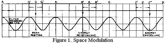
Referring to Figure 1, A, B, C, D, represent the fixed train of pulses while G, H, J, represent the train of variably phased pulses, the phasing of which may be varied between the limits G' to G", H' to H", J' to J". The spacing is such that
AG = 5/8 AB.
AG' = ½AB
AG" = ¾AB
If the pulses are transmitted with the variable pulses at their mean position, a signal will be given by the filter at a certain level. When the variable pulses are moved towards the positions G', H', J', the energy supplied by the fixed pulses is reinforced, raising the filter output level, but when they are moved towards the positions G", H", J", they will subtract from the fixed pulse energy and reduce the filter output level, giving
complete cancellation with zero output at those limiting points.
For morse transmission, the variable pulses are keyed to the positions G", H", J" for the "space" periods and to G', J' for the mark periods.
For tracking, a Lorenz type beam signal is simulated by continuous modulation by dots and dashes on the 1064 c/s tone. Dots indicate that the aircraft is at less than target range and dashes at greater than target range, their modulation depth being set at 100% by the ground operator when the controlled aircraft is farther than 0.1 miles from the required track. Within this distance from the track the modulator is switched to automatic control. This varies the modulation from 100% at 0.1 miles off track to zero modulation when the aircraft is exactly on track. In practice, 10% modulation is approximately the lowest variation of the equisignal that is discernible. This is given when the aircraft is about 20 yards off track, so that the apparent beam is one of 40 yards from edge to edge.
The automatic control of the modulation is secured at the ground station by the use of a differential detector, usually referred to as the "double strobe" circuit.
This comprises two associated strobes of 4 microseconds width, spaced apart by 1 microsecond, developed from a variable strobe on the main measuring time base which triggers the magnified time base. The double strobe is thus locked to the magnified time base, but can be positioned by manual control at any distance along it, being displayed thereon by intensity modulation to provide the target range marker. (The centre of the double strobe is set at the target range). The double strobe is used in a differential gate circuit, which develops a D.C. voltage of amplitude and sign determined by the overlap of the aircraft response with either or both of the strobes.
This D.C. voltage is used to balance or unbalance in the required direction a dot-dash modulator circuit, which controls the excursions of the variable pulse train; modulation being thus produced directly by the position of the aircraft response within the double strobe.
To maintain accuracy of calibration for use with the double strobe circuit a pulse of constant amplitude and width is derived from the front edge of the aircraft response, since this response is liable to fluctuate in amplitude and width with varying radio signal strength.
The front edge of the aircraft response is sensibly free from fluctuations from this cause and hence the derived pulse gives an accurate measure of the position of the aircraft relative to the ground station.
A description of the double strobe circuit, illustrated in Figure 2 follows:‑
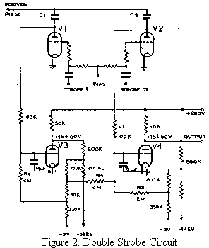
V1 and V2 are normally cut off by a negative potential applied to their control grids. The arrival of signals at the anodes at tines other than those at which the bias is removed, will not cause current flow through the valves. The bias is lifted periodically by the double strobe pulses, so that V1 is made conducting by the first 4 microsecond pulse and V2 by the second 4. microsecond pulse.
V3 and V4 are used as direct-coupled feedback amplifiers. In the absence of outputs from V1 and V2, V3 and V4 are conducting, the grids being at -2 volts and the Figure 2. Double Strobe anodes resting at +145 volts.
The circuit operates in the following manner.
Suppose a derived signal pulse is applied to the anodes of V1 and V2 at the same time as the second of the double strobe pulses is applied to the grid of V2. Anode current will flow in V2 for the duration of the overlap of the derived signal and double strobe pulse, and the anode side of the condenser C2 will be charged negatively.
At the termination of the signal pulse, current will flow through R1 and R2, to discharge the condenser, so that the grid end of R2 becomes negative causing a rise in anode voltage of V4. The feed-back is so proportioned that when the derived pulse fully coincides with the strobe pulse, the anode voltage rises by 60 volts above +145 volts.
Similarly, if the derived pulse coincides with the first strobe pulse, the anode voltage of V3 will rise by 60 volts.
In the feedback circuit in the anode of V3, a point is chosen, to which R3 is connected, which goes positive by nearly the voltage developed at this point by the discharge current from C1.
The difference is the small change in grid voltage required to produce a change of 60 volts at the anode.
R4 is connected to a point in the network nearer the anode, such that any change in the anode voltage of V3 will be accompanied by an equal and opposite change in voltage on the anode of V4.
If the derived signal lies equally between the two strobe pulses, the two effects on the grid of V4, will cancel out and the anode will remain at +145 volts. As the signal moves to one side or the other, the anode voltage of V4 varies with the movement from +145 volts, up or down with a maximum swing of 60 volts to either side.
It is this change, of D.C. voltage, which as explained earlier, controls the dot-dash space modulator.
OBOE MARK I - ANTI-JAMMING AM INTERFERENCE
When Oboe Mark I was first-passed, in the summer of 1942, to 109 Squadron of the newly formed Path Finder Force, two channels were provided, each having a single radio frequency common to the ground to air and the air to ground links as shown in Fig. 3.
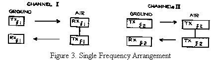
The recovery time of the airborne apparatus was made long enough to prevent re-triggering by reflections from the ground or neighbouring aircraft.
Soon after the training of the Squadron in the use of Oboe was started, much interference with the communication system was encountered from random pulse transmissions in this country and it was found impossible to locate and suppress these.
To overcome the effect of the interference the "K" system (K for coincidence) was devised and introduced for training purposes.
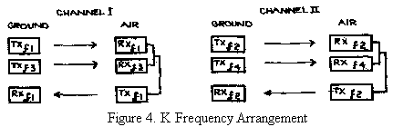
This system consisted of the radiation of coincident pulses on two radio frequencies from each ground station to two receivers in the aircraft, the outputs of these being fed to a coincidence stage which was used to trigger the aircraft transmitter and the communication filter.
The coincidence stage provided that only signals received on the two frequencies simultaneously were operative, and since the chance of two simultaneous interfering pulses on different radio frequencies is small, the effect of the interference was greatly reduced and training was able to proceed. Fig. 4 shows the arrangement of the four radio frequencies that were used for the two channels.
At the end of 1942, when Oboe was first used operationally, the single frequency system was tried and in the operational areas, was found to be completely free from interference, continuing so for about six months.
Due to the visual display the ground stations could tolerate quite a heavy degree of pulse interference, but trouble
was anticipated at the Dover stations from C.W. jamming from the French coast, particularly from the powerful jammers at Cap Gris Nez.
To counter this, at both southern ground stations, a second receiving array was installed, steerable towards the jamming source.
The signals from this second array were fed through a variable attenuator and phasing line and mixed with the signals from the normal receiving array.
The variable attenuation and phasing were controlled by an operator so that the interfering signals from each array were equal in amplitude but 180° out of phase with each other.
Since there was usually a considerable angle between lines drawn from the Oboe stations to their operational areas and to the jammers, almost complete cancellation of the jamming could be made at the expense of a slight reduction in wanted signal.
Throughout the life of Mark I, skilful manipulation of this anti-jamming device prevented all but a few operations being spoiled by ground jamming.
During the summer of 1943 the aircraft communication channel began to suffer from random interference in the operational areas, so the "K" system was introduced for operations.
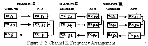
At the same time a third channel was introduced by making use of the existing four radio frequencies re-arranged as in Fig 5.
After about a year of operation, pulse interference in the 200250 Mc/s band became very heavy and after analysis it was seen that in the presence of such interference matters were being worsened by consequent mutual interference between the Oboe channels themselves due to the use of common frequencies in the K groupings.
The groupings were re-arranged and it was arranged for the aircraft to respond on frequencies other than those on which they received. The new arrangement is not shown as considerable variations were made from time to time as conditions demanded.
The introduction of a third channel often led to Oboe aircraft on separate channels making their runs very close to each other and in this event the transmission from one aircraft could provide a high enough field strength to break into both receivers of another aircraft and thus develop simultaneous pulses at the coincidence stage, resulting in cross-modulation of channels.
To prevent this happening, it was arranged that instead of the pulses being made coincident on two frequencies for each channel, they were separated by 7 microseconds, and the coincidence circuits in the aircraft were modified to accept only pulses of this spacing.
Eventually the advent of new channels on Oboe Mark II made it possible to withdraw one Mark I channel and ease the interference problem by a more suitable separation of frequencies for the two remaining channels.
Early in 1944 it became apparent from the symptoms of some of the Mark I failures that C.W. jamming was being experienced. Special investigation flights were made confirming this and it was found that the C.W. was modulated at a frequency of 50 to 100 c/s.
Until this time the diode second detector of the aircraft receivers had been directly coupled to the succeeding video amplifying stage and thus this stage could be blocked by the reception of quite a small C.W. signal.
This coupling was changed to a condenser resistance coupling of small time constant so that the first element to overload was the diode detector.
At the same time the I.F. gain was reduced so that the diode could be worked on a lower part of its slope to make it less susceptible to overloading by C.W., the sensitivity of the receiver being compensated by increase of video gain.
Interference with the Oboe communication channel becomes intolerable long before the signals returned to the ground become too badly affected for efficient measurement of range to be made, and it was thought that an alternative communication channel might preserve the system efficiency during many cases of jamming.
Suitable transmitters of about 2 K.W. output in the M.F. band were available for location at the Oboe ground stations and use was made of these, the required modulation being obtained from the outputs of aircraft type filters driven from the Oboe ground transmissions.
In the aircraft M.F. receivers were installed, the outputs of which could be switched into the filter as an alternative to the normal Oboe drive.
This scheme, though promising, was never very successful owing to the difficulty of finding a frequency in the M.F. band free from interference.
However, the various modifications permitted Mark I to continue quite efficiently in the target areas outside the Ruhr but with a varying degree of efficiency in the Ruhr area where interference was often severe.
Shortly before the invasion of France, following the destruction of nearly all the enemy radio installations in the occupied territories (very often by the aid of Oboe), all interference with Mark I in these areas disappeared and during the advance of the battle towards Germany the efficiency of its early operational days was restored.
When only German targets remained, the jamming was so intense that operations became impossible with Mark I and it was withdrawn from operational use in 1944, its life of nearly 2 years having greatly exceeded all early expectations.
In connection with this account, a recent interview with an enemy scientist who, during the war, had been engaged in Radio Countermeasures, particularly against Oboe, was of considerable interest.
He explained that it took the enemy seven months to associate Oboe signals with bombing raids, as they had no information or apparatus to guide them. (Only one Mark I airborne equipment fell into their hands and that was almost completely destroyed in the crash of the aircraft which carried it.)
Oboe signals were heard at Calais in 1942, but statistics had seemed to connect them with E boat activity in the Channel.
In June-July 1943 the signals were detected over the Ruhr, and for the first time were definitely associated with the dropping of bombs.
A team was formed to think out how Oboe might work and how it might be jammed.
Towards the end of 1943 a very large number of CHL type M.C.W. jammers were erected in the Ruhr and in this area the jamming was eventually considered to be very effective, as indeed we ourselves found it to be.
Outside the Ruhr (to which all importance was attached) difficulty was experienced in securing a sufficiency of skilled crews to make the jamming as effective.
At intervals from the end of 1943, ground jamming was tried from the French coast but the effort was abandoned through lack of success, a tribute to the efficacy of the anti-jamming arrays and the skill of the 60 Group operators.
No attacks were made on the ground stations as it was considered that a multitude of reserve stations would be available.