1. Historical Background of Oboes Mark IIM and III
Oboes Mark IIM and III are the outcome of an investigation into the use of centimetre waves for Oboe purposes which began in 1941 at about the same time as the first work on the 200 Mc/s Mark I system. The chief object of this parallel investigation was to shadow Mark I with a system less liable to be seriously jammed than one in the vulnerable 200 Mc/s band. It had been predicted that Mark I would be jammed out of all usefulness within a month of starting an operational career. Although, because of its vulnerability it was at first intended to confine this system to experimental and training work, urgent needs of the RAF eventually caused a change in this decision and Mark I entered the Battle of the Ruhr. Very surprisingly and fortunately (for us) the jamming attempts against even this elementary system were not particularly successful until about 18 months later.
By this time the centimetre technique had been mastered. The new centimetre systems filled the gap immediately and effectively, much, we are now told, to the despair of the strong Oboe counter-measures organisation which the enemy had by this time built up.
2. The Centimetre Waves and Oboe
2.1 Suitability of Centimetre Waves for Oboe
It was considered that the use of frequencies in the 10 cm. band would render Oboe very difficult to jam. At the outset, however, it had to be proved that this wavelength was generally suitable for Oboe purposes.
Oboe, apart from using radar principles to measure the range and velocity of a transponder equipped aircraft also provides a ground to air communication link for the passage of this information to the aircraft. These functions demand good .and steady signal to noise ratios at operational range. Even with the highest flying aircraft available this would for most targets be about optical range.
In 1941 very little was known of the limitations to the use of 10 cm. signals for transmission of information over long distances. It was anticipated that good results could only be expected within the optical horizon with perhaps a small increase due to diffraction and refraction. Knowledge of what anomalous effects (for example the effect of clouds) might occur in the "good" zone and their significance relative to centimetre wave communication was very incomplete. Tests, therefore, had to be made to find out whether there were any serious obstacles to the development of this band for Oboe purposes.
2.2 Early Centimetre Test Flights
Wellington was fitted with a 10 cm. receiver and, using a 5 KW magnetron transmitter on the ground, a number of test flights were flown. These were to determine the range, under various conditions, over which useful pulses could be received in the aircraft.
Considerable changes in signal strength, usually of a fairly regular nature, were noticed even at small ranges. At optical range signal strength tended to be poor and the observed fluctuations would have made communication impossible. An encouraging result, however, was that the amplitude of fading appeared to vary with the type and position of the aircraft aerial. It seemed likely that an interference pattern was produced by reflections from the various surfaces of the aircraft. Movement of the aircraft would cause changes in this interference pattern with the result that the aerial might drift from time to time between successive nodes and antinodes.
A dipole mounted in a small paraboloid was fitted to the tail of the Wellington to look backwards. With the aircraft flying radially away from the ground transmitter it was thought that this aerial system would not suffer from interference effects, the reflecting surfaces of the aircraft being screened from the dipole by the paraboloid. Workable pulses were received with this system up to optical range.
It has now been fairly conclusively shown that, provided a suitable aerial system is found for the aircraft, with the transmitter power and aerial gain used in centimetre Oboe there are no difficulties in maintaining a 10 cm. communication (i.e. information transferring) system between ground and air within ranges up to 1.1 times the optical horizon appropriate to the heights of the aircraft and ground station.
2.3 Application of Centimetre Waves to an Oboe System
Having once ensured that centimetre waves were suitable for Oboe, a system had to be devised utilising this waveband. An airborne transmitter and receiver had to be designed along lines suitable for a moderate production programme. These could simply replace the 200 Mc/s transmitter and receiver in the aircraft. On the ground, a station could be made by exchanging the transmitter, receiver and aerial system of a Mark I station for their 10 centimetre equivalents. This step was actually taken at the time when jamming of Mark I became acute, the resultant ground stations being known as Mark IIF.
Other work had been done, however, on a system not only incorporating centimetres but also improving on Mark I in other respects. The chief improvements were,
(a) the number of aircraft which could be simultaneously controlled was increased by making it possible to control several aircraft at a time on one radio frequency.
(b) new circuits were employed in an attempt to improve accuracy.
Oboes Mark IIM and III are derived from this system. The only major difference between these two Marks being that IIM
uses mobile ground stations and III uses fixed stations. Identical airborne equipments are used by each.
3. Definitions of Nomenclature
3.1 Definition of an Oboe Sub-Channel
Two ground installations, a Cat and a Mouse, located at points a considerable distance (say, 100 miles) apart are required to control an Oboe aircraft. These installations transmit on a common radio frequency but at different P.R.F's. A single aerial system and receiver can therefore be used to receive both transmissions in the aircraft and. separation of the two signals is achieved by discrimination between the two P.R.F's. In Mark I, for example, the Cat and Mouse installations always used P.R.F's of 266 and 194 p/s respectively.
For the purposes of this article a single link which can be defined by its radio frequency and its P.R.F., between a ground installation and an aircraft, will be called an Oboe sub-channel. It follows that two Oboe sub-channels are required to control an aircraft.
Most Oboe ground stations are equipped to produce several sub-channels simultaneously, so, for the purpose of clarity, that portion of a ground station concerned with the production of one sub-channel will be called an Oboe ground installation. Each ground installation is equipped with means whereby it can function as either Cat or Mouse.
3.2 Traffic Handling Capacity
The traffic handling capacity of an Oboe system is the maximum number of aircraft which the available ground equipments can simultaneously control over a single target area. Four radio frequencies in the 200 Mc/s waveband were allocated for the use of Mark I. Combined with the two P.R.F's used, this provided 8 Oboe sub-channels with a traffic handling capacity
of 4 aircraft. (Use of the double frequency "K" system described by A.J. Blanchard in the article on anti-jamming measures in this issue might have raised the effective number
of sub-channels to 12 and the traffic handling capacity to 6). Clearly this maximum limit had to be raised in subsequent Oboe systems.
4. Two Techniques Peculiar to Marks IIM and III.
4.1 The Multi-P.R.F. Technique
Whilst only two P.R.F's (194 p/s and 266 p/s) were employed, the number of sub-channels on a given radio frequency could only be two, one Cat and one Mouse, supplying one aircraft only. During the time spent in developing the Mark IIM and III ground stations work had also proceeded upon the development of a circuit capable of discriminating between P.R.F's to a high degree of accuracy. The circuit produced is now commonly called the P.R.F. selector. It is capable of selecting a wanted P.R.F. from unwanted P.R.F's where the separation is as small as 4 p/s (at Oboe P.R.F's of the order 100 - 200 p/s).
With the aid of the P.R.F. selector in the aircraft, it became possible to increase the number of sub-channels on a given radio frequency by radiating them at different P.R.F's. At first 8 and subsequently 12 P.R.F's were allocated and could all be used on each of three 10 cm. radio frequency channels which were adopted. Using 8 P.R.F's 4 aircraft could be handled simultaneously on a single radio frequency. This represents a useful improvement in traffic handling capacity over that obtained with Mark I.
An incidental but important advantage also obtained by the use of this technique was that the highly discriminative airborne selectors would make enemy jamming even more difficult. To obtain reasonable success the jammer would have to radiate on at least one of the P.R.F's (or a harmonic of one of the P.R.F's) used by each of the Oboe aircraft engaged. The measurement and duplication of the P.R.F. would have to be fairly accurate.
4.2 Width Modulation
In order to get sufficient discrimination between unwanted and wanted P.R.F's in the multi-P.R.F. system the airborne P.R.F. selector makes use of a gating valve which is opened just before the anticipated arrival of a pulse of wanted P.R.F. and closes again at the end of that pulse. In this way it is arranged that the two P.R.F's designated to an aircraft are separated from the unwanted ones.
The necessary control information from Cat and Mouse installations is sent to the aircraft in Morse code marks and spaces. For this purpose some form of modulation of the pulsed transmissions from the ground installations is necessary. Because of its suitability for use with the gate valve method of P.R.F. discrimination, width modulation of the transmitted pulses is used.
The normal pulse width of a ground station is 4µS. When it is necessary to send a message in Morse code, a switch is thrown causing the pulse width to change to 1 µS. The message can then be sent out by means of a standard Morse key arranged so that whenever it is pressed, the width of the radiated pulses reverts from 1 µS to 4µS.
Fig. 1 illustrates how the Morse letter A (dot-dash) would be transmitted by this system.
The period of preliminary 1µS pulses is followed by a train of 4 μS pulses constituting the dot. This is followed by the space consisting of a train of 1 µS pulses. The dash consists of a long train of 4 µS pulses and is followed by a series of 1 μS pulses which are terminated by the throwing of the previously mentioned switch which restores the steady transmission of 4μS pulses. Although the dot and dash are shown as consisting of 20 and 60 pulses respectively, the number of pulses in a given Morse character would in practice depend upon the speed of transmission of the character and the P.R.F. of the station.
Two demodulators are used in the aircraft. One demodulates the signal from the Cat station, as distinguished by its P.R.F., and feeds the information content in the form of an amplitude modulated 1000 c/s tone to the pilot's headphones. The other demodulates the Mouse signal and supplies the observer's headphones with information in a similar manner. Each demodulator is adjusted to give maximum audio output when the received pulse width is 4 μS and to give proportionally less output as the pulse width diminishes until at a pulse width of 1 µS, the audio output just becomes zero. Further reduction of the pulse width would then have no effect. During the transmission of a Morse signal, in the manner illustrated in Fig.1, the recipient in the aircraft therefore hears the marks (dots or dashes) at maximum volume and the periods of 1 μS transmission produce intervening spaces of complete silence.
As is generally the case in range measuring radar devices, the front edges of the transmitted and received pulses are used as reference lines for range measurement. So that this facility is not lost, the modulation of the pulse width is made to change only the phasing of the back edges of the transmitted pulses. Irrespective of pulse width, the front edges are transmitted at instants determined only by the P.R.F. of the station.
4.21 Width Modulation at the Cat Station
Three possible types of track signal may be radiated from a Cat installation according to the position of the aircraft, as follows:‑
(a) When the aircraft is on the track circle, pulses of a constant width of 4 μS are radiated.
(b) When it is inside the track circle, pulses width modulated to give dots are radiated.
(c) When it is outside the track circle, dashes are radiated.
The tracking dots and dashes differ from the Morse characters previously described in that their loudness relative to the intervening spaces has to serve as an indication to the pilot as to his distance off-track. The mark-constituting pulses continue to be transmitted with a width of 4 µS but the space-constituting pulses are given, at any time, a width which is less than this by an amount which is proportional to the distance of the aircraft off track at that time. The modulation depth therefore increases as the Aircraft gets further away from the required track. The modulation characteristic of the Cat station is such that at about 0.25 mile off-track the space-constituting pulses have a width of 1 µS. Because the airborne demodulator gives silence at this pulse width and below, there is no point in increasing the modulation depth any further and for greater distances off track the space-constituting pulses continue to be of 1 µS duration. Limiting circuits in the ground equipment secure this result.
Since, by convention in this system, 1 µS and 4µS represent the minimum and maximum pulse widths radiated, it is convenient to describe the depth of modulation when the space-constituting pulses are 1 µS wide as being 100%, and where the swing of pulse width is less than 3 µS to express it as a direct ratio of this. Thus when the space-constituting pulses have width ω µS then the depth of modulation, m, is given as a percentage by:-
m = (4 - ω)/(4-1) x 100%.
Fig. 2 shows a typical modulation curve for a Cat installation when used for circular tracking. Percentage of modulation, as defined above, is plotted against distance of the aircraft off-track.
Pulses of widths between 1µS and 4 µS produce a note in the pilot's headphones of an amplitude which is roughly proportional to the excess of the pulse width over 1 µS. By making a continuous mental comparison between the loudness of the marks and the loudness of the spaces the pilot is able to estimate his distance off track and his rate of movement towards or away from the track. The nature of the marks, whether dots or dashes, indicates on which side of the track he is flying.
During the course of an operation it is necessary at intervals to send routine instructions in Morse. This is done as described in the previous section. The preliminary throwing of the switch to give 1 µS pulses also cuts out any tracking modulation which is being transmitted.
5. The Airborne Equipment
Fig. 3 shows a block diagram of the latest airborne equipment. Common T & R is used and the same wide angle aerial serves for reception from and transmission to, both ground stations. There are two outputs from the receiver. The first of these feeds the P.R.F. selector with all received signals, the second passes on signals of selected P.R.F. to modulate the transmitter.
5.1 The P.R.F. Selector
Fig. 3 shows that the P.R.F. Selector consists of two similar parts, gate valves 1 and 2, gate pulse generators 1 and 2 and demodulators 1 and 2, together with the gate pulse mixer which is common to both parts. The reader is referred to Mr. D.E. Bridges article "The Pulse Recurrence Frequency Selector" in 'this journal, in which the principle of the selector is described, The Selector Unit actually used in an aircraft includes two P.R.F, selectors, set respectively to the designated Cat and. Mouse P.R.F's.
 The gate pulse mixer mixes the gating pulses of both P.R.F's and the combined series of pulses is fed to a further gating valve in the video section of the receiver.
Pulses of one of the required P.R.F's pass via gate valve 1 to demodulator 1 and of the other P.R.F. via gate valve 2 to demodulator 2. The function of the two demodulators is to convert the width modulation of the incoming Cat and House signals into dots and dashes which are fed to the pilot's and observer's headphones.
5.12 The Principle of the Demodulation Method Employed
Fig. 4. shows the demodulating circuit used.
In this circuit the gate valve V1 of the P.R.F. selector is normally cut off so that diode V2 is non-conducting. The condenser C2 is therefore charged, the potential of plate A (see Fig. 4) being +140V and that of plate B being that of the slider of potentiometer R3 which is normally below 70V. The values of R1 and C1 are such that the anode potential of V1 falls about 70 volts in 1 µS whenever a pulse is accepted by the gate. Thus pulses of 1 μS or less do not cause V2 to conduct. Wider pulses do, however, and C2 is discharged by an amount roughly proportional to the excess of the pulse width over 1 μS. The plate B of C2 thereafter assumes a potential which exceeds its normal value by a proportional amount.
V4 is normally cut off but has fed to its grid sharp, positive pulses coincident with the front edges of the P.R.F. selector gating pulses. These occur about 50 μS before each expected P.R.F. pulse. The effect is to cause V4 to conduct and condenser C2 is recharged to its normal level so that it is ready to be newly discharged by each P.R.F. pulse. Fig. 5(a) shows a series of width modulated P.R.F. pulses with various degrees of modulation. Fig.5(b) indicates the phasing of the recharging pulses fed to the grid of V4. and (c) shows the resultant modulation envelope appearing at plate B of C2 as a result of the demodulation of the P.R.F. pulses shown at (a).
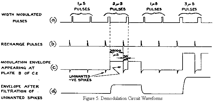
The unwanted negative-going spikes are of about 50 μS duration but with the normal P.R.F's, used they are spaced about 5000 - 10,000 μS apart. They are therefore readily removed by a low pass filter without serious detriment to the envelope to be extracted, Fig.5(d).
In practice the resultant square wave is fed to the suppressor grid of a valve with a 1000 c/s waveform fed to its grid. The resulting 1000 c/s anode current is therefore amplitude modulated in accordance with the suppressor waveform. In a pair of headphones, transformer coupled to the anode circuit of this valve the demodulated signal can be heard as a 1000 c/s note of variable amplitude. The potentiometer R3 (Fig.4.) can be adjusted so that 1 μS pulses produce silence in the headphones and potentiometer can be used to adjust the sensitivity until 4 μS pulses produce maximum 1000 c/s output.
5.2 The Airborne Receiver
To allow for radio frequency differences between the two ground sub-channels which have to be simultaneously received an I.F. bandwidth of about 9 Mc/s is employed, the mean I.F. being about 14Mc/s. This bandwidth also implies good preservation of pulse-shape for signals on or near the correct
radio frequency. Waveform preservation is important for exact determination of range and the video stages are also designed to maintain pulse-shape. These stages include a delay network of about 4 μS delay such that the front edge of a pulse does not reach the video output until the back edge has passed through the I.F. stages. Video pulses are fed to the receiver gate valve. This rejects all pulses except those which occur during, the period of application of a gating pulse from the gate pulse mixer. Thus only pulses of the correct two P.R.F's pass through the gate to the pre-modulator stages. (Together with interfering pulses if any of these occur within the gate period).
The pre-modulator stages feed suppression pulses to the I.F. valves so that any pulse which passes through the gate suppresses the receiver (for a period which is actually somewhat longer than the pulse duration). The object of the 4μS delay network mentioned previously is to prevent the application of suppression from cutting off the back edges of any pulses up to 4μS duration. Amplified versions of the pulses getting through the gate valves are fed from the pre-modulator to the transmitter modulator stages.
5.3 The Airborne Transmitter
An American A.S.G. transmitter with slight modifications
is used. The pulses fed by the receiver to the modulator
still bear the width modulation impressed at the ground station.
This is removed in the modulator by means of a delay line and
the retransmitted pulses are of 1.3 μS duration. Selected
pulses are repeated from the aerial after a total delay of
about 6μS.
The 10 cm. magnetron used is the American 2J54 which is tuneable and has an output of 40 kw peak, pulsed at 12 KV. The transmitter unit also includes the local oscillator, crystal mixer and I.F. head amplifier.
6. The Ground Equipment
6.1 Differences between Mark ID and Mark III Ground Stations
The Mark IIM system employs mobile ground stations. The equipment required to produce a single sub-channel is housed
in a trailer. (Radio Vehicle 434A). A station for the production of more than one sub-channel is obtained by setting up the required number of trailers at one site. Provided they use different P.R.F's, these can operate simultaneously on one radio frequency. If different radio frequencies are used then the same P.R.F. can be repeated.
The Mark III stations are fixed and consist of several (usually 4) single sub-channel installations housed in one building. By bringing the different installations into close proximity and due to the fixed nature of the station certain parts of the equipment can be shared between sub-channels. In particular a single master crystal oscillator is used as the basis of range calibration and P.R.F. production for all the installations. Since the P.R.F's are obtained by dividing down the frequency of this crystal oscillator the pulses at different P.R.F's are phase linked due to their common origin. In Mark IIM separate oscillators are used and their outputs inevitably drift in phase relative to one another. There is therefore no phase linking. The airborne filters work equally well with both systems.
There was an attempt to use a common receiver and a common transmitter for all the sub-channels of a Mark III station. This involved mixing all the pulses of different P.R.F's and with their different information contents, prior to the modulator of the transmitter. To get good signal strength at the aircraft a beamed aerial system employing a 4ft. paraboloid had to be used. When controlling several aircraft simultaneously, however, it was found that the distribution of the aircraft was usually such that only one or two could receive favourable signals at a time.
A separate aerial system, receiver and transmitter are now used on each sub-channel. The aerials are beamed for long distance work and directed individually towards their appropriate aircraft by bracketting on the received signal. Common T and R is used. The need for bracketting and also for working over different targets possibly widely spaced in azimuth, with bean aerials, necessitates the use at both Mark IIM and Mark III stations of rotatable aerial systems.
6.2 The Oboe Ground Installation in detail
Fig. 6 shows in block diagram form the main units of an Oboe ground installation for the production of a single sub-channel. The diagram is applicable to
Mark III except that in the case of Mark III the master crystal oscillator would also be connected to the calibrators of the other sub-channel installations forming the station.
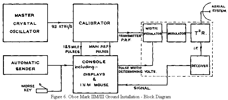
The functions of the units shown are as follows.
6.21 The Master Crystal Oscillator
This oscillator produces an output waveform with a frequency within 5 c/s of 93.117 Kc/s. The stability is about 5 parts in 106. A high standards necessary to ensure that the range calibration pulses which are generated from the output waveform will be accurate and free from variation. To ensure stability, the crystal is maintained at a constant temperature by means of a thermostatically controlled oven. The frequency 93.117 Kc/s will be recognised as having a period equivalent to 1 radar mile.
6.22 The Calibrator
The function of the calibrator is to utilise the incoming 93.117 Kc/s alternating voltage from the oscillator for the production of
(a) Range calibration pulses for the displays of the installation.
(b) P.R.F. pulses for triggering the time bases - subsequently referred to as the main P.R.F. pulses.
(c) P.R.F. pulses for-triggering the transmitter, delayed 5 miles (i.e. about 50 μS) behind the time base triggering P.R.F. pulses. These are subsequently referred to as the transmitter P.R.F. pulses.
1 mile calibration pulses are generated from the 93.117 Kc/s alternating voltage by the normal technique of squaring and differentiating to obtain narrow pulses. To simplify interpretation of the displays every 5th 1 mile calibration pulse is amplified to a greater extent than its neighbours. This is achieved by means of a phantastron dividing circuit dividing the 1 mile frequency by 5 and feeding a gating pulse at the new frequency to an amplifying valve dealing with the 1 mile pulses. The gain of this valve is thereby raised for every 5th pulse. The mixture of 1 and 5 mile calibration pulses thus obtained is fed to the displays located in the console.
The main P.R.F. pulses are obtained by division of the 5 mile calibration frequency. This frequency is about 18.62 Kc/s and since it is desired to use P.R.F's lying between about 90 and 170 p/s the division ratio must be between about 200 and 100. Division by such large numbers with circuits of normal stability necessitates the use of two division stages in series. They are known as the 1st and 2nd P.R.F. dividers.
Normally such a two stage divider would not be capable of division by prime numbers. It can, however, be shown, that, using the multi-P.R.F. system of sub-channel discrimination, the interference ratio between sub-channels can be kept to a minimum if the P.R.F's are obtained by dividing the mother-frequency (i.e. 5 mile frequency in this case) by prime numbers. Prime number division has been obtained with the two stage P.R.F. divider in the Oboe calibrator by a process known as feedback which will be described later.
The delayed transmitter P.R.F. pulses are obtained by gating the next 5 mile calibration pulse after each main P.R.F. pulse and using these for transmitter triggering. Since the main P.R.F. pulses themselves roughly coincide in phase with 5 mile pulses (from which they are obtained by division) the transmitter P.R.F. pulses have a delay of about 5 miles relative to the main P.R.F. pulses.
Gating of the required 5 mile pulses is achieved as follows. A. phantastron circuit with a delay of about 75 μS (7½ miles) is triggered by the main P.R.F. pulses. The screen waveform of this phantastron is slightly delayed by means of an RC circuit and fed to the suppressor grid of a valve having 1 and 5 mile pulses fed to its grid. Normally the grid and suppressor of this valve are biassed so that no anode current flows. The positive gating waveform fed to its suppressor raises the bias sufficiently for a 5 mile pulse but not the smaller 1 mile pulses to cause anode current to flow. Thus the single 5 mile pulse occurring in each gating period appears at the anode of the gate valve and after amplification is fed via a cathode follower to trigger the sub-modulator of the transmitter.
The use of the gating technique rather than a straightforward 50 μS delay has the advantage that phase variation of the transmitter pulses relative to the calibration pulses is eliminated. It will have been noticed that a gating method is also used to produce a mixture of 5 mile and 1 mile calibration pulses. This avoids the difficulty of phasing up which would arise if the output of the 5 mile divider were used to produce narrow 5 mile pulses and an attempt were then made to mix these with the 1 mile pulses.
6.221 Use of Feedback to Obtain Prime Number Division in the Mark IIM Calibrator
The 1st and 2nd P.R.F. dividers consist of anode triggered phantastrons the 1st being triggered by negative going 5 mile pulses and the 2nd by the negative going front edges of the cathode waveform of the 1st. Thus the negative going front edges of the cathode waveform of the 2nd divider will be roughly coincident with every (p1 x p2) th 5 mile pulse, where p1 and p2 are the division ratios of the 1st and 2nd dividers respectively (p1 and p2 must be integers).
If a negative going waveform of sufficient amplitude be fed to the suppressor grid of the pentode in a phantastron circuit after triggering has taken place, the anode quickly returns to its quiescent condition and the full phantastron cycle does not take place. The circuit will retrigger on the first triggering pulse to arrive after the removal of the negative voltage from the suppressor grid.
The principle of feedback is to feed a negative waveform to the suppressor grid of the 1st P.R.F. divider pentode during its first division period after the production of each P.R.F. pulse by the 2nd divider. By adjusting the phase of this negative pulse the 1st divider can be made to divide by any number r less than p1 in its first period of division. If it then goes on to divide by p1 p2 times before the 2nd divider retriggers, the overall division ratio is r + p1 x p2.
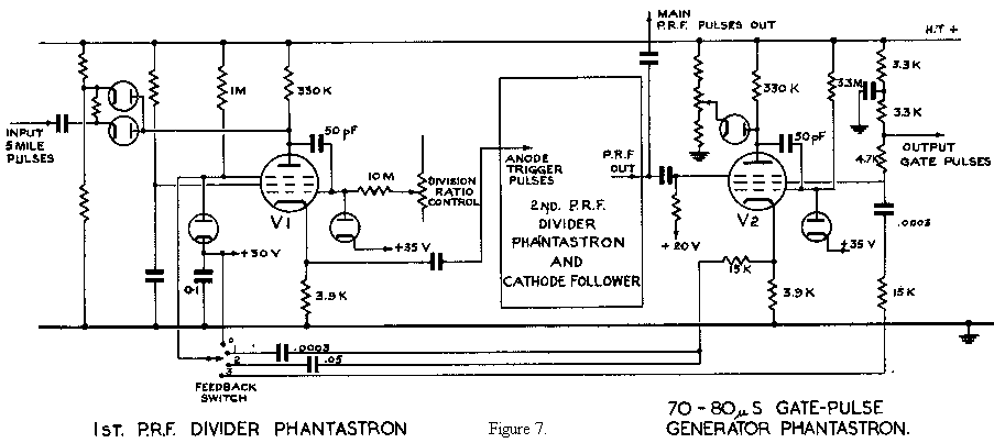
Fig. 7 shows diagrammatically the relevant portion of a Mark IIM calibrator. Since the 2nd P.R.F. divider and the subsequent cathode follower do not enter very fully into the description they are shown only in block.
The pentode, V2, shown, is that of the gate pulse generating phantastron described earlier and concerned with the gating of the first 5 mile pulse after each main P.R.F. pulse.
The suppressor grid of the pentode V1 in the first P.R.F. divider may be connected by means of the feedback switch shown, to either
(a) + 20V D.C.
(b) The cathode of V2 via a capacity of .0003 μF.
(c) The cathode of V2 via a capacity of .05μF.
(d) The screen of V2 via a capacity of screen .0003 μF.
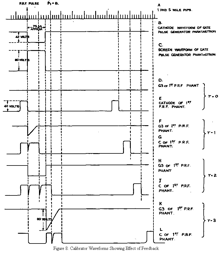
Fig. 8 shows at A a series of 1 and 5 mile pulses, one of which corresponds to a P.R.F. pulse. At B and C are shown the corresponding cathode and screen waveforms respectively of V2. The remainder of Fig. 8 shows how cases (a) (b) (c) and (d) above, give values of r equal to 0, 1, 2 and 3 respectively.
It will be noted that in case (b) differentiation is used to reduce the effective length of the feedback waveform, the unwanted positive going edge being eliminated by the diode connected to the suppressor. In case (d) it is the positive front edge of the screen waveform which is removed by the diode and the duration of the negative pulse following the back edge is such that r becomes 3.
With the three values of feedback available, all the required prime number division ratios between 100 and 200 can be produced.
6.23 The Console
This unit contains the range measuring displays and, as its name implies, is the main operating position of the installation. It can be divided into a number of smaller units the chief of these being the two time base units and the two mouse units.
The time bases are a long time base (L.T.B.) and a magnified time base (M.T.B.) which are displayed on separate 12" cathode ray tubes. The L.T.B. has a forward sweep duration equivalent to about 400 miles and is triggered upon the arrival of each main P.R.F. pulse from the calibrator. A switch is provided so that either the received signals or 5 and 25 mile calibration pips can be displayed on this time base. The calibration pips are generated from the 1 and 5 mile output of the calibrator by means of an auxiliary circuit in the console. The two displays are illustrated in Fig.9.
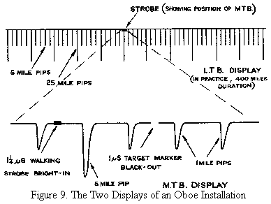
The M.T.B. is a fast time base which is used for displaying in detail any desired section of the L.T.B. A switch provides the choice of three forward sweep speeds corresponding to 15 miles, 8 miles and 3 miles. Using the last of these any 1 mile section of the L.T.B. can be extended to a length of more than 10 cms on the M.T.B. trace. A strobe on the L.T.B. (see Fig.9) indicates the section of this which is shown on the M.T.B. Its position along the L.T.B. is determined by two delay circuits, the 5 mile selector and the 1 mile selector. These work in series so that the total delay of the strobe is equal to their added delay. They are both variable, adjustment of the first causing the strobe to jump along the L.T.B. in 5 mile intervals and adjustment of the second, in 1 mile intervals. By locking the back edges of these two delays to 5 and 1 mile calibration pulses respectively possible jitter of the M.T.B. when strobing out at long ranges along the L.T.B. is eliminated.
The two mouse circuits consist of the mouse strobe unit and the mouse computer unit. The first of these is triggered by the back edge of the 5 mile selector delay waveform and produces two strobes, the target marker strobe and the walking strobe. By suitable adjustment of the 1 mile selector these can be observed on the the first as a 1 μS blackout and the second as a 1¼ μS bright-in as shown in Fig. 9.
The two units together form the Instantaneous Velocity Measuring Mouse and are more fully described by Mr. W.L. Roberts in his article on Mouse systems in this issue. In the console the mouse computer unit has a dual function. When the installation is producing a mouse sub-channel it predicts, from information fed in, the instant at which bomb release should occur. When a cat sub-channel is being radiated the same circuit, slightly rearranged by the throwing of a switch, originates the dot and dash waveforms necessary for the track signal. The function of the circuits in the mouse condition is fully described by Mr. Roberts.
6.23.1 The I.V.M. Mouse Circuits used for Catting
With the walking strobe locked to an aircraft signal, the range voltage produced by the mouse strobe unit is equal to +165V when the aircraft is at target range. It varies at a rate of about 33 volts per mile as the range of the aircraft changes, being less than 165V when the aircraft range is less than the target range and above 165V when the aircraft range exceeds the target range.
Thus Vr = 165 + 33R
Where Vr volts = range voltage
and R miles = residual range of the aircraft. This is the difference between aircraft range and target range, being negative when the aircraft is at a less range than the target.
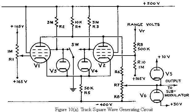
In order to produce tracking signals the range voltage is compared with +165V by means of the circuit shown in Fig.10(a) which is a modified long-tailed-pair circuit. A steady voltage of 165V is fed to the grid of V1 and a voltage equal to (165 +⅔ x 33R) volts is fed to the grid of V2. In Fig.10(b) curves3 are drawn showing the variation of the cathode currents of the two valves as the grid voltage of V2 is varied about +165V. These curves are deducible if it be remembered that the common cathode potential must be slightly higher than that of the higher grid potential. Assuming that the contacts of relay SW are for the time being disconnected the corresponding anode currents would be as shown dotted.
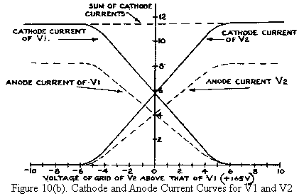
It can be seen that when the two grids are at equal potentials the two anode currents are equal (this assumes balanced valves and other components) and that for small inequalities of grid volts the valve with the higher grid potential carries an anode current greater than that of the other by an amount roughly proportional to the grid volts difference.
The function of the relay SW is to earth one or other of the two suppressor grids, according to whether it is energised or de-energised. Since the cathodes of V1 and V2 have a potential of about +165V, earthing of one of the suppressors cuts off the anode current of the valve concerned, the total space current then being taken by the screen. If the relay be alternately energised and de-energised by feeding a square wave to its solenoid the anode currents of the two valves will flow alternately in the 10K anode load. The D.C. volts across this resistor will therefore have a square wave superimposed with amplitude equal to the difference between the two anode currents. As can be deduced from Fig.10(b) the maximum amplitude of the square wave will be about 80V when the grid potential difference is greater than about 6 volts, falling to zero when the grids are at equal potentials. The square wave fed to the relay solenoid has actually an on-off ratio of 1:4. The anode square wave therefore has a peak to trough ratio of 4:1 or 1:4 according to whether the range volts are less than or greater than 165V.
The anode voltage is too high to be of use but a suitable voltage is obtained from the slider of potentiometer R7. The two diodes V5, V6 limit the output voltage swing applied to the width modulator of the transmitter to the range +10V to +30V. An output of 10V causes the production of 4 μS pulses and an output of 30V the production of 1 μS pulses. The slider of R7 is adjusted so that when the grid potentials of V1 and V2 are both +165V, the output voltage is 10V, with valve V5 removed. This ensures an on-track pulse width of 4 μS. When the range volts differ from +165V the voltage at the slider of R7 would, in the absence of V5, swing above and below +10V. The presence of V5 eliminates voltage swings below 10V thus ensuring that the mark constituting pulses are of 4 μS duration.
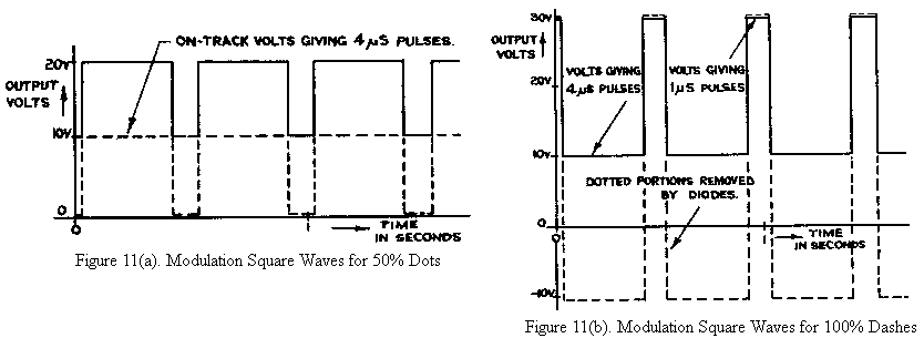
The waveforms shown in Fig. 11 are the output square waves obtained for an aircraft (a) 0.1 mile inside the track circle (b) 0.25 mile or more outside the track circle. The dotted parts of the waveforms indicate portions removed by the limiting diodes V5 and v6. The two chosen distances off track correspond to 50% dot and 100% dash modulation as shown in Fig.2 in the section 4.2 on width modulation.
6.24 The Automatic Sender
It has been mentioned in section 4.2 that Morse code signals can be transmitted over an Oboe sub-channel.
Many of the messages sent during an operation are of a routine nature and are invariably used in every operation. For brevity these have been reduced to one letter codes. The automatic sender enables any of these codes to be sent by merely selecting the letter required on a selector switch and then pressing a button. The initial switching from 4μS to 1 μS pulses then takes place automatically as does the actual keying of the message.
6.25 The Transmitter-Receiver Unit
Apart from the width modulator the receiving and transmitting circuits are of conventional type. In Mark IIM installations the magnetron used is the 2J54 with a peak output power of 4.0 KW. Mark III installations use an output power of about 200 KW.
The width modulator is the unit in which the width modulation is applied to the pulses driving the transmitter modulator. The width modulated pulses are actually generated by a phantastron type circuit. The phantastron is suppressor triggered by the transmitter P.R.F. pulses and the width of the output pulses is varied over the range 4 μS to 1µS by variation of the potential of the cathode of the anode catching diode. The incoming modulating D.C. square waves from the console are transformed to a suitable potential level by an amplifying stage, which also reverses their phasing.
The width modulated pulses produced are then amplified and fed into the modulator which is designed so as to introduce as little width distortion as possible so that the R.F. pulses are width modulated in accordance with the D.C. modulating waveform.
6.26 The Aerial System
The R.F. output of the magnetron is fed to the common T and R aerial which consists of a dipole at the focus of a 4 ft. paraboloid. For operation at short ranges, at which this arrangement would produce too narrow a beam over the target area, it is usual to broaden the horizontal diagram by placing two sheet metal screens over the front of the paraboloid, one on either side, so that a vertical aperture of about 1 ft. wide and 4 ft. high remains at the middle. In order to facilitate removal of the mismatches produced, an impedance matching section is included in the feeder line.
The aerial system has variable azimuth and elevation so that the aircraft under control can be bracketted in both planes, remote control from the console position being provided by Selsyn Motors. The setting of the aerial in azimuth and elevation is continuously displayed to the console operator by means of a magslip repeater system.