INTRODUCTION
Ultrasonic devices have been used at TRE for two main purposes:‑
The usefulness of the ultrasonic method for both these applications depends upon the slow velocity of ultrasonic waves (mechanical vibrations) compared with that of electromagnetic waves.
The velocity of ultrasonic waves in water is 1.5 x 10⁵ cms/sec, which, within the limits of measurement is identical with the value found for waves of audio frequency.
Thus in order to obtain a time delay of 1 millisecond we require a path length of 1.5 x 105 x 10-3 = 150 cms in water. A delay cell using piezo crystals for transmitting and receiving and separated by 150 cms of water can be made in a reasonably convenient form whereas a purely electrical delay of this magnitude and with a comparable frequency response would be prohibitively large.
Velocity of ultrasonic waves in water 1.5 x 10⁵
Velocity of electromagnetic waves in air = 3 x 1010= 1/200,000
Hence so far as range measurement is concerned we can use ultrasonic devices to make model radio systems to a scale of 200,000 to 1 or rather less 1 cm to 1 mile which is a convenient scale for radar trainers.
We will consider the behaviour of generators and receivers of supersonic waves; some of the properties of those waves and the effect of the media in which they travel and how these effect the design of supersonic devices.
The particular application to trainers is discussed in a separate article.
GENERATORS AND RECEIVERS
Ultrasonic waves may be generated and communicated to liquid and solid media by
Of these the first method is the only one which has been used at TRE and only quartz has been used. X-cut quartz crystals have been found suitable at the high frequencies which are necessary and the constant properties of quartz, its resistance to moisture and availability in a pure form give it many practical advantages over tourmaline or Rochelle Salt which from other considerations may be more suitable. It is found possible to predict the characteristics of devices using quartz crystals with a high degree of confidence. In order to obtain a good frequency response it is necessary to use a carrier frequency and to modulate this with the required waveform.
The quartz crystals used for transmitting and receiving are X-cut and execute longitudinal vibrations (i.e. along the axis). The useful bandwidth which can be obtained can be expressed as a fraction of the carrier frequency and so the latter is made as high as possible. It can be shown that so far as bandwidth is concerned there is no advantage in using crystals operating on harmonics so that the thickness of the crystal which can be used sets a practical limit to the frequency. The attenuation in the supersonic medium is approximately proportional to the square of the frequency and this may also have to be considered in deciding the best frequency for any practical purpose.
Carrier frequencies of around 10 Mc/s have proved practical performance as before and delay cells using 18 Mc/s have been made crystals for frequencies above 13 Mc/s are very fragile and the manufacture crystals with higher fundamental frequencies becomes increasingly difficult.
Quartz Crystals as generators and receivers
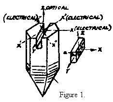
X-cut slabs are cut from a single crystal as shown in Figure 1 with the thin dimension which governs the resonant frequency normal to the X-axis. The X-faces are covered with a conducting coating of metal by sputtering or otherwise: it is important to ensure that the metal chosen for the coating will not be corroded by the acoustic medium.
It is possible to find a value for the input electrical impedance of an X-cut crystal vibrating with both faces in contact with non-reactive mechanical loads.
We can use the two piezo electric relations to find the impedance in terms of the mechanical force and the displacement of the crystal faces and combine this with mechanical considerations to obtain the electrical impedance in terms of known mechanical quantities.
The two piezo electric equations either of which can be derived from the other are:‑
V/ ℓ = 1/ε • Fp/S ..........................................(1)
Q = ε • S (z1 -z2)/ ℓ .....................................(2)
where V is the voltage developed by a force Fp acting across the crystal.
Q is the charge developed by a compression of (z1 -z2)/ ℓ
z1,z2 are the displacements of the crystal faces
ℓ is the crystal thickness
S is the area
ε = piezoelectric constant = 4.77 x 10⁴ if force is measured in dynes and electrical quantities in esu
It will be noticed that in these equations voltage is related to force and charge to displacement. Consideration of any mechanism for the piezoelectric effect suggests that this is a more logical method of statement of the experimental facts than the common one which related charge to force and potential to displacement.
It allows us to consider the piezoelectric impedance of a vibrating crystal independently of the electrostatic capacity of the crystal.
From (1) and (2)
Zp = V/i = (ℓ² Fp) / (ε²S² d/dt (z1 - z2) ) = (ℓ² Fp) / (ε²S² j•ω (z1 - z2) ) = ℓ²/ε²S² ω • Fp/(U1 -U2) ................(3)
This equation gives the relation between the piezo -electric impedance in terms of the ratio of the force applied to the crystal faces to the relative velocities of these faces.
We can also find this ratio from mechanical considerations in terms of the acoustic impedance of the media in contact with the crystal faces.
We can thus find the following expression for the piezoelectric impedance.
Zp = ℓ² a1 a2 - j•a•(a1 + a2) cot ωℓ/c + a² ...............................(4)
ε²S² (a1 + a2) + 2j•a (cosec ωℓ/c = cot ωℓ/c)
It should be pointed out that in the derivation of the dynamical equation it is assumed that the vibrations consist of plane waves and lateral notion has been ignored. The force due to attraction of the electric charges has also been neglected.
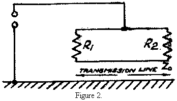
This expression for the piezo-electric impedance corresponds exactly with the equivalent circuit of Figure 2 if the values of the elements are as given below.
The close analogy between acoustic wave relations and electrical line equations can also be used to show that this must be the equivalent circuit of the crystal.
Thus we can compare the acoustic relations:‑
Force = F = ρCS = √ ρS/1/GS = Acoustic impedance,
Velocity Uand c = √ GS/ρS
with the analogous eletrical relations:-
Potential = V = Zo = √ L/C
Current Iand c = √ 1/LC
We have therefore an analogy between Force and Potential, between Particle Velocity and current and between the characteristic acoustic impedance of the medium and the characteristic impedance of an electrical line.
It is moreover clear from Equation (1) and the differentiated form of (2) that not only is Potential analogous to Force and Current to particle velocity but that in a piezo-electric plate the electrical quantities are proportional to their mechanical counterparts.
Since, then, we are using a mechanical half wave crystal it is readily seen that the equivalent circuit must be represented by an electrical half wave line fed at its ends as in Figure 2 in which R1 R2 represent the characteristic impedance of the lines which are the electrical counterparts of the acoustic media in contact with the crystal faces. The constants in equations (1), (2) and (3) give the values of the equivalent electrical quantities. The values of the equivalent circuit elements are:‑
Zo = ℓ²a = ℓ²ρc
ε²S² ε²S²R1 = ℓ²a1 = ℓ²ρ1c1
ε²S² ε²S²R2 = ℓ²a² = ℓ²ρ1c1
ε²S² ε²Sℓo = ℓ Co
c
where:-
Zo = characteristic impedance of electrical line
ℓo = length of electrical line
co = velocity in electrical line
ℓ = thickness of quartz crystal
ε = piezoelectric constant
S = area of crystal
a = acoustic impedance of quartz
a1 = acoustic impedance of medium 1.
c2 = acoustic impedance of medium 2.
APPROXIMATE EQUIVALENT CIRCUITS FOR SPECIAL CASES
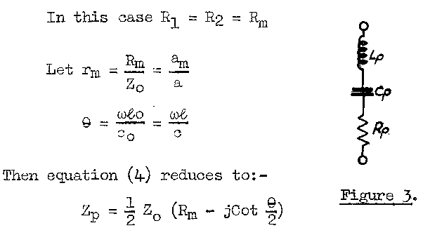
Case 1 Symmetrical loading
In this case, R1 = R2 = Rm
Let rm = Rm = am
Zo = aθ = ωℓo = ωℓ
co c
Then equation (4.) reduces to:-
Zp=½ Zo (Rm-jCot θ/2)
which represents the impedance of an open circuited line in series with a resistance and having series resonances at
θ = (2n - 1) π or ℓ = λ/2, 3λ/2 ..... etc.
It can be shown that for frequencies near to resonance the equivalent circuit is approximately represented by the series circuit of Figure 3 if the values of Rp, Cp, Lp and Qp are as shown in Table I.
The alternative expressions in the table have been found by making use of the design formula for a λ/2 crystal
f = 2.87 x 10⁵ /l
c = 2fℓ = 2 x 2.85 x 105 = 5.74 x 10⁵ cms/sec.
| TABLE I | ||
|---|---|---|
Operation at λ/2 |
Operation at 3λ/2 |
|
| Cp | 8ℓ = 8.2 ×10⁻²¹ Sf Farads π² cZo |
8ℓ 9π² cZo |
| Lp | ℓ Zo = 3.1 × 10¹⁸ Henrys 8c Sf ³ |
ℓ Zo 8c |
| Rp | ½ Rm = 1.63 × 10¹³ (ρm cm)/Sf ² ohms | ½Rm |
| Q | T • ρc = 1.19 × 10⁶ 4 ρm Cm ρm Cm |
3π • ρc 4 ρm Cm |
Case 2 Unsymmetrical light loading
If we consider r1 and r2 botrh very much less than unity equation (4) can be reduced to
Zp = R1 + R2 (1 - j 2 Cot θ/2)
4 r1 + r2
and again for frequencier near the resonant frequency this apporximates to the circuit of Figure 4 if
Rp = ¼(R1 + R2) = (ℓ² / 4ε²S) (ρ1 c1 + ρ2 c2)
Qp = π = π • ρc
2 (r1 + r2) 2 ρ1 c1 + ρ2 c2Cp = 8 = 2ε² S
πωo Zo π² f ² ℓ³ρLp = π Zo ℓ³ρ
8 ωo 8ε² S
The approximation to the simple series circuit is not very accurate if the difference between r1 and r2 is large. The formulae can be used for the case of light loading on one side of the crystal only by putting r2 = 0 and are sufficiently accurate for many design purposes if r1 is less than, say 1/10.
Effect of the Electrostatic Capacity of the Crystal We have shown that the piezo-electric impedance can be approximately represented by the simple series of Figure 3 and the input impedance of the crystal will consist of this series circuit in parallel with the electrostatic capacity of the crystal as in Figure 3.
Cp = kS e.s.u. where k= permittivity of quartz in the X direction and ℓ = thickness of crystal
if ℓ = ½λ = c
2 foCo = kS fo = fo S × k = fo S × 4.55 = 1.26 × 10⁶ foS e.s.u. = 1.40 × 10⁻⁶ foS micromicrofarads
2πc 2πc 2π × 5.74 × 105In the circuit of Figure 4 the capacitance ratio
Co k π c² 4.55 × 2.65 × 5.45² × 1010 × 5.74 ×1010 = 150
Cp 32 ε² 32 × 477² × 108
This ratio depends only on the properties of quartz for a crystal working on the nth harmonic the ratio is increased by factor of n2.
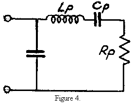
In Figure 4, Rp is the radiation resistance of the crystal and we usually wish to dissipate the maximum power in Rp. The high admittance of Co takes most of the current fed into the terminals of Figure 4 and even if Co is tuned with a parallel inductance at the midband frequency the high capacitance ratio of the crystal seriously limits the effective bandwidth which can be obtained.
The Effective Area of the Crystal
It is found that there is very little coupling between different elements of the crystal face. The assumption that only those portions of the crystal which are plated and are thus in the electric field will vibrate is found to be valid for all practical purposes. There must, of course, be some lateral movement at the edges of the plated portion but it is found that a ring round the edge of the crystal can be left free from plating and can be stuck to metal holders without affecting the characteristics. If this edge which is stuck to the crystal holder is plated the performance by the device is seriously affected because these portions of the crystal will have a different Q and will not only ring but may also give rise to reflections from other parts of the holder.
TABLE II |
||||||
|---|---|---|---|---|---|---|
WATER (ρC = 1.45 x 10⁵ C.G.S. units) MERCURY (ρC = 1.98x10⁶) |
||||||
Loading on one face. |
Loading on both faces. |
Loading on both faces. |
||||
| 1 Mc/s | 10 Mc/s | 1 Mc/s | 10 Mc/s | 1 Mc/s | 10 Mc/s | |
| Zo | 2.46 pF | 24.6 pF | 2.46 pF | 24.6 pF | 2.46 pF | 24.6 pF |
| Cp | .0164 pF | .164 pF | .0164 pF | .164 pF | .0164 pF | 1.64 pF |
| Lp | 1.55 Henrys | 1.55x10⁻³ Henrys | 1.55 Henrys | 1.55x10⁻³ Henrys | 1.55 Henrys | 1.55x10⁻³ Henrys |
| Rp | .58 Mohm | 5.8 Kohm | 1.16 Mohm | 11.6 Kohm | 16.1 Mohm | 161 Kohm |
| Q | 16.7 | 16.7 | 8.35 | 8.35 | 0.6 | 0.6 |
PRACTICAL CASES
It is interesting to take some possible cases and find the magnitude of the elements in Figure 4.
In each case the effective area of the crystal is 2 sq. cms and we shall consider water and mercury.
The value of the equivalent circuit elements are given in Table II.
The simple equivalent circuit is not applicable to a crystal with mercury on one face only and the complete formula must be used. It can be shown, however, that the crystal will continue to resonate at the frequency corresponding to oscillations and this applies so long as the acoustic resistance of the medium is less than twice that of the crystal.
Circuits for feeding the crystal
The crystal is usually inserted in the anode circuit of a pentode which approximates to a constant current source.
We have seen that the capacitance ratio Co/Cp seriously limits the band-width over which power can be dissipated in R. There is evidently an optimum value for the Q of the equivalent series circuit which will give the best overall bandwidth. If the Q of this circuit is too high the bandwidth will be limited accordingly, whereas if it is too low the parallel circuit containing the electrostatic capacity of the crystal will take a proportionately greater share of the current at frequencies removed from the mid band frequency. An improvement in bandwidth at the expense of efficiency can however, be obtained by the use of either of the circuits of Figure 5.

The characteristics of these circuits can conveniently be expressed by Universal curves drawn in terms of the parameters mQp and 1/Qp2 C1/Cp and here
m = ω/ωo - ωo/ω
A number of these curves from which specific cases can be calculated have been given in TRE Report T.1358.
The circuit of Figure 6(a) has been found useful and the actual response curves obtained agree with the calculated curves: it is usually necessary to compromise between the desired bandwidth and the power loss which can be tolerated.
The same curves can be used for the circuit of Figure 6(b) or 6(c) when the QS of the two halves of the circuit are the
same, if we use the value
1/Q2 . C1/(CVp + C3) for S.
In practice the circuits indicated by Figure 6(b) and (c) are satisfactory, but the adjustments are rather critical.
The Optimum Value for the Q of the Crystal
We have seen that there must be an optimum value for the Q in order to obtain the best performance. Wider bandwidths than those obtainable directly can then be obtained, at the expense of power loss, by the circuits mentioned above.
We can consider the equivalent circuit as a section of a simple type of band-pass filter for which there will be a definite value of the terminating impedance Rp for zero reflection.
The value for this optimum impedance is governed by the ratio Co/Cp and is therefore fixed by the constants of quartz. In order to obtain the best characteristics therefore we should choose the acoustic impedance of the medium to give the correct termination.
Moreover if we can use the correct value for R and provide the correct electrical circuit for the receiving crystal all the energy incident on the receiving crystal will be absorbed.
It happens that water which has also certain other desirable properties has an acoustic impedance which is fairly close to the optimum value.
The Use of Mechanical Transformers
We can, however, use any suitable medium for transmission provided that we can transform the impedance to give the correct load on the crystal.
We can use the electrical line analogy to show that a λ/4 thickness of a material of suitable acoustic impedance can be used to transform the impedance of the medium to the required impedance. Some preliminary experiments have been made in the use of such mechanical transformers which show that the method has possibilities but a further knowledge of the acoustic properties of materials is needed before much choice is available.
Measurement of Crystal Impedances
If the input capacitance and equivalent shunt resistance of a crystal with one or both faces in contact with water are measured by means of a bridge the values are similar to what would be expected in accordance with the simple equivalent circuit although some departure can be seen at frequencies far from resonance. These departures from the simple equivalent circuit are less when the crystal is symmetrically loaded. The departures are sufficiently great to cause some difficulty in assigning a value for the Q of the equivalent circuit from the shape of the capacitance curve alone which has maximum and minimum values for frequencies removed by f/2Q from the resonant frequency. A better value for the Q of the crystal referred to the simple equivalent circuit can be obtained from the gradient of the capacitance curve at the resonant frequency if the equivalent shunt resistance can also be measured accurately.
Although refined measurements have not been made, the measurement of crystal impedances over the band of frequencies near resonance has proved profitable and has been a pointer to many improvements in the details of crystal mounting and plating.
It was found for instance that consistent and reproducible impedance curves could only be obtained when the plating was such that the whole of the plated portion of the crystal was really in contact with the liquid and there was no undamped-but-energised portion of the crystal at the edges, and when the crystal face was free from bubbles formed from dissolved air.
Departures from smooth regular impedance curves have often indicated a point that had been overlooked and the fruitfulness of such measurements cannot be overstressed.
We may point out that reproducible impedance measurements can only be expected if care is taken to avoid reflections from the walls of the measuring tank or if these are eliminated by using a pulse modulated carrier for the measurements.
The Radiation Pattern of the Crystal
We have seen that it is convenient to use high supersonic frequencies, and frequencies of around 10 Mc/s have been found suitable for use in delay cells and trainers.
The velocity of waves of this frequency in water is found to be about 1.5 x 10⁵ cms/sec. which is the same as for low frequencies.
The wavelength of 10 Mc/s sound in water is (1.5 x 10⁵) / 107= .015 cms.
It is evident that unless we use very small crystals, which would be difficult to handle and to feed electrically, the radiation patterns will be very narrow.
Circular crystals of about 16-18 mms diameter are convenient for delay cells as a consideration of the impedances will show: this diameter is seen to be about 100λ.
The effective polar diagrams of the crystals as transmitters and receivers can be compared with those for aerials of very large aperture and it is evident that transmitting and receiving crystals require to be accurately parallel. The radiation from the transmitting crystal will consist of approximately plane waves and the receiving crystal must not only intercept the beam but must be accurately parallel to the wave front.
The aperture is not only large compared with the wavelength but in some cases is also appreciable compared with the distances between transmitter and receiver and Fresnel diffraction phenomena must be considered.
Owing to the small lateral coupling between different elements of live crystal area it appears that the response obtained from a quartz crystal receiver can be computed by vector addition of the disturbances incident on all parts of the crystal surface. It is therefore desirable that the phase of the radiation shall be as uniform as possible.
Optimum Size of Crystal for Delay Cells
If we consider first, points on the axis of a transmitting crystal a consideration of Fresnel Diffraction shows that as we move away from the crystal we shall find alternate points of maximum. and minimum intensity until we come to a point where the transmitting crystal can be divided into one "half period element" only and thereafter there will be a continuous
decrease in intensity. The distance V from a crystal of radius R which only one half wave element remains is given by:‑
V= 2R2 / λ = 85 cms if λ =015 cms and R = 0.8 cms.
In delay cells we must also use a receiver of finite size and for a given distance between the crystals which should certainly be greater than 2R2 / λ there corresponds an optimum size of crystal. Thus if the receiver crystal is so large that it intercepts the whole of the first Fresnel maximum the outer edges of the crystal will be contributing very little to the final response but the associated electrostatic capacity is as we have seen disadvantageous.
It can be shown that for maximum power transfer the crystals shown should be of equal radius "a" where a = 0.43λ.r and that the power efficiency is then about 65%.
PROPERTIES OF THE TRANSMISSION MEDIUM
Reflection and Refraction
Ultrasonic waves are reflected and refracted at material boundaries.
Reflection at a plane boundary takes place so that the angle of incidence is equal to the angle of reflection.
At visual incidence the ratio of reflected to incident energy depends upon the acoustic impedances of the media on either side of the boundary (see Table for representative values). If the acoustic impedances of the media are a1 and a2 the ratio of reflected to incident energy is given by:‑
E = (al - a2)2
E (al + a2)2
Thus for normal incidence at a steel:water (or water:steel) boundary Ei/Er 88% and for a distrene water boundary the coefficient is 6%.
| TABLE III | ||
|---|---|---|
| Velocity cms/sec | Acoustic Impedance ρc gms cms-2sec1 | |
| Water | 1.5 x 10⁵ |
1.5 x 10⁵ |
| Distrene | 2.3 x 10⁵ |
2.45 x 10⁵ |
| Mercury | 1.46 x 10⁵ |
19.8 x 10⁵ |
| Steel | 6.1 x 10⁵ |
47.5 x 10⁵ |
The angle of the refracted ray is given by Snell's Law:‑
Sin i = c1
Sin r c2
The refracted ray is bent towards the normal if the velocity of the second medium is less than that in the original medium. Thus if a wave travelling in water is incident on the plane face of a piece of steel the direction of travel will be bent away from the normal and this also applies if the second material is distrene. Although both these substances are denser than water the greater elasticity causes the velocity of the supersound to be greater and we must beware of comparing these materials with what are commonly referred to as dense media in optical work.
The phenomenon of total internal reflection also occurs and when a wave is incident on a plane boundary of a medium in which the velocity is greater than that in which it is travelling there is a critical angle of incidence beyond which all the energy is reflected and none is transmitted to the "harder" (high velocity) medium. This angle is sin-1c1/c2. For water: steel it is sin-1.246 = 14°15' and for water:distrene it is sin-1 .652 = 40°42'.
This phenomenon is very useful because it permits reflectors to be used in ultrasonic systems with the certainty that there will be complete reflection and no trouble due to multiple reflections inside the material composing the reflector.
The Use of Lenses
Supersonic lenses for use in water have been constructed from distrene. Distrene was chosen because of its comparatively low absorption and because the velocity of ultrasound in it had been measured enabling the radii of curvature to be calculated for any desired focal length.
By using a small source of ultrasonic waves it was found easy to verify the ordinary lens formulae and to concentrate on the image point all the power radiated from a small source; by this means much larger echoes were obtained from a small reflector at the image point than could be obtained without the lens or by using a larger crystal energised with the same power.
A mirror can also be used and this does not suffer from the disadvantage of internal reflections which are troublesome with lenses.
Absorption
The absorption of ultrasonic waves is usually found to be proportional to the square of the frequency and the rapid increase of attenuation with frequency is one of the difficulties in the way of using high frequency supersonic devices. There are however applications where some supersonic absorption is desirable, such as delay cells which are not correctly terminated and in which serious trouble would be caused by multiple reflections in the cell if these were not reduced by the absorption of the medium.
Most ultrasonic devices have used liquids but some consideration has been given to the possibility of using solids. There was thought to be no a priori reason why solids should have a much greater attenuation than liquids and some experiments were made at TRE in the hope of obtaining some pointers which would be useful in choosing suitable media for supersonic transmission.
Absorption in Liquids
There are several theories of ultrasonic absorption most of which lead to the result that the absorption is proportional to the square of the frequency. The most well known theories of ultrasonic absorption are those of Stokes which relates the absorption of the "viscosity" of the material and that of Kirchoff which explains the loss by assuming that heat is conducted from those parts of the material which is heated by compression to the adjacent cooler parts. These theories give a square law variation of loss with frequency and both are undoubtedly operative. The Stokes' "Viscosity" term is however always many times the "heat conduction' term. The values of absorption calculated on the basis of these
theories is, however, many times lower than that found experimentally. Either the "viscosity" or "internal friction" is very different from the values measured by the normal methods or different mechanisms of loss are also operative. There might at certain frequencies be an increased absorption due to the mechanical relaxation time of the material but there are very few substantiated cases in which the loss frequency curves have been found to show a maximum.
The values of measured absorption coefficients given in the literature often disagree and the most reliable guide seemed to be to study comparative values on a large number of liquids all measured by the same worker using the same method. Thus the results of G.W. Willard can be taken as a guide to the comparative absorption coefficients of different liquids. These figures certainly do not appear to show any obvious correlation between acoustic absorption and other properties but indicate that water and alcohols have lower absorptions than most liquids measured. The tremendous difference between benzene and xylene is very striking and is completely inexplicable in terms of normal viscosity.
The table below shows four examples taken from Willard's results.
| TABLE IV | ||||
|---|---|---|---|---|
| αα/f2 | α 10 Mc/s | Velocity cm/sec. | Loss/m -sec | |
| Glycerine | 26 x 10-15 | 2.6 | 1.986 x 10⁵ | 4.480 db |
| Benzene | 8.3 x 10⁻¹⁵ | 0.83 | 1.295 x 10⁵ | 935 db |
| M-Xylene | 0.78 x 10⁻¹⁵ | 0.078 | 1.325 x 10⁵ | 91.6 db |
| Water | 0.33 x 10⁻¹⁵ | 0.033 | 1.500 x 10⁵ | 28.8 db |
The last column gives the loss in db per millisecond of time delay and is derived as follows:‑
The Power loss is given by P =Poe-2αx ..............α is the
amplitude absorption coefficient
Therefore Loss in decibels = 10 log10 P/Po = 10/2.3 loge e-2αx = 8.7αx
The measurement of attenuation in water delay cells appears to agree well with the figures in the above table but by running the cell at a temperature of around 73° which we shall show to be desirable the attenuation falls to about 15 db per millisecond.
Absorption in Aqueous Solutions
We shall see that water and aqueous solutions arc peculiarly suitable because it is possible to work at temperatures at which they have zero temperature coefficient.
It is usually found that the attenuation in water is raised by dissolving other substances in it, but it is not greatly raised by alcohols or by Urea. Ionic solutes usually appear to raise the attenuation considerably.
Temperature Coefficient of Velocity in Liquids
Water appears to have a lower absorption than any known liquid and has usually been used for delay cells.
The early experimental delays, however, were very unstable and required a considerable amount of A.V.C. to compensate for the variable performance. The variation in amplitude of response far overshadowed the variation in the actual time delay.
This instability was largely due to the fact that the velocity at all parts of the beam was not the same and hence the disturbance arriving at the receiver crystal was not a plane wave, but one in which the phase of the radiation varied over the surface of the receiving crystal and which also varied from time to time owing to the temperature fluctuations and convection currents.
If due to convection there is an even temperature gradient over the cross-section of the tube it will be seen that the liquid column will act like a prism and we may get a sharp diffraction minimum instead of the central maximum.
The velocity of supersound in water is, however, found to have a maximum value of about 1.55 x 10⁵ cms/sec at 73°C* and stable delay cells can be made if this temperature is used.
Most other liquids have a negative temperature coefficient and it was desired to obtain a mixture which would have a zero temperature coefficient of velocity at room temperature. Various solutions with water were made and it was found that the curve relating the velocity with the temperature was always approximately parabolic but that the maximum value appeared at a lower temperature with increasing concentration. Thus solutions of Urea, Alcohol, Glycerine and common salt can be made with zero temperature coefficients at room temperature if the correct concentration is chosen.
The most suitable of these solutes is ethylene glycol on account of its low tendency to evaporate, the fact that it is non-corrosive and has low supersonic absorption. A concentration of 350 gms per litre has maximum velocity at 32°C and a concentration of 400 gms per litre at 16°C.
It is interesting to note from an American report that workers at the Bell Telephone Laboratories had independently come to similar conclusions and have further found that not only can the temperature at which the velocity maximum occurs be controlled but also by adding a third component the actual value of the maximum velocity can be controlled within limits.
* It is interesting to note that the values calculated from the density and the compressibility measured statically at different temperatures also indicate a maximum value at about 70°.
Solids as Transmission Media for Delay Cells
Although water delay cells operating at 73°C have been found to be reliable and stable it is worth enquiring whether
solid media could. be used because many obvious practical advantages would accrue.
It is interesting at this stage to compare some of the measures in terms of which the attenuation of sound in solids can be expressed.
We can express the losses during a mechanical compression cycle by the damping capacity of the substance which is the ΔE/E ratio of the energy last to the mean energy, by the mechanical QE, or by the constant β in the relation β.Fm2 which gives the frictional loss in terms of the amplitude stress of the cycle.
These quantities are related as follows:‑
ΔE/E = 2π/Q = β.q = 2αλ where q = Young's modulus
a = Amplitude absorption coefficient
If the absorption coefficient of a solid is proportional to the square of the frequency we see that the Q of a bar of the material vibrating in the longitudinal mode should be inversely proportional to the frequency, for
Q = π/αλ = πf/αc = π/ckf where k = α/f2
In the applications of ultrasonics in which we are most interested at TRE the important quantity is the loss measured in decibels for a given time delay and we have already seen that the loss in db per unit length is 8.7 αx.
So Loss per second = 8.7 αc
= 8.7 = πf/Q = 27.3 f/Q. • decibels
If Q is inversely, proportional to the frequency
Loss per second = (27.3 f²)/fm Qfm where Qfm is the Q at a frequency fm.
Thus the product of the Q and the frequency at which it is measured should provide a factor of merit for a substance for use in solid delay lines.
There is very little information available on the damping properties of solids largely because of the difficulty in making measurements on account of the problem of eliminating losses in the supports for the specimen. The published figures for the damping capacity of steel undergoing torsional strain for resistance, vary by a factor of over a thousand.
Although, therefore, we cannot place any great reliance on recorded measurements it is interesting to see what order of Q is required in order to give a reasonable supersonic attenuation at 10 Mc/s. Let us take the approximate absorption in water at 10 Mc/s as 15 db per millisecond and find the Q: in order to compete with water as a good medium solid substances should at least have a Q of the same order.
For water fm Qm = (27.3 x2 x 1011)/15 x 103 •=• 2 x 10¹¹
Thus the Q is approximately 20,000 at 10 Mc/s.
If the loss in water is proportional to the square of the frequency over the full frequency range the "Q" of water would therefore be 200,000 at 1 Mc/s, 2,000,000 at 100 Kc/s etc.
It is seen immediately that it will not be easy to find solid substances with Q's of this order at comparable frequencies if the Q really is inversely proportional tp the frequency. The Q of a good tuning fork is about 104 at 1 Kc/s but it is not known how much this could be increased by eliminating air damping and losses in the support. The Q's of steel rods in torsion have been found as high as 2 x 10⁶ for law frequency torsional oscillations though measured values are usually quoted as very much greater than this.
The highest known mechanical Q's are found for quartz crystals and fibres of fused quartz are also known to have very low damping.
It would appear that fused quartz is the most likely material to have low absorption for high frequency supersonic waves but that metals, glasses or plastic materials might be found suitable if there is a change in the mechanical properties at high frequencies. Some explanatory experiments were made at TRE using rods of material with 10 Mc/s piezo crystals fixed to the ends for transmitting and receiving.
The materials tested were:‑
(a) PLASTICS
Distrene Lucite, Bakelite pressboard etc.
(b) MICALEX
(c) METALS
Steel, brass.
(a) FUSED QUARTZ
It was found that fused quartz was a suitable material and the losses appeared to be of the same order as those in water and possibly less, though more careful work would be needed before a definite value could be quoted. Steel and brass and Micalex were all found to be capable of transmitting supersonic waves but the inhomogoneities of the material were found to give rise to reflections which would always cause trouble at the short wavelengths used.
Distrene, Lucite and pressboard were all found to transmit with varying degrees of absorption. For distrene which has the lowest absorption of these, the loss appears to be less than 1 db per microsecond. The loss in distrene is thus the same order as that in Benzene showing that there is no wide gap between the absorption in liquids and solids. Distrene has an acoustic impedance which is a little greater than water and would therefore be suitable where the loss is not important. It is possible that other grades of distrene or similar plastics could be found with a lower specific loss.
The Possible Use of Fused Quartz for Delay Lines
The acoustic impedance of fused quartz is of course too high to be used for making delay cells unless an acoustic transformer can be used to transform this impedance to a lower value suitable for feeding from the generating crystal.
We have seen that water has approximately the optimum impedance for the purpose and we should therefore expect success by using a λ/4 transformer whose acoustic impedance is √ (ρC)fused quartz x (ρC)water or approximately 4.3 x 10⁵ CGS units.
Preliminary experiments were made using oil films and varying the thickness of the film. It was found that by using .002" films reasonable input impedances were obtained and that delays could be made which would transmit 2 microsecond pulses reasonably satisfactorily. A delay line was also made using a film of gelva cement to stick the crystal firmly to the fused quartz rod using strands of 47 SWG enamelled wire as spacers. Such a delay appeared to have possibilities but some development work would be needed before delay lines of this type could be made with confidence.
In particular it would be necessary to develop a suitable technique for sticking the crystals and to discover the most suitable material for use as a transformer cement.
If the difficulties could be overcome and the losses in quartz were in fact found to be sufficiently low, very neat delay lines might be designed. Furthermore if a method of "connecting" two quartz surfaces together without discontinuity in impedance could be devised "preset" or even "variable" solid delay lines might be made.
The experiments were made on fused quartz because it was thought that this material was likely to have a lower attenuation than other solids, but it is possible that glass might also be suitable though the constant chemical composition and properties of fused quartz would appear to give it a definite advantage.
The Velocity in Fused Quartz
The velocity in fused quartz was found to be 5.6 x 10⁵ cms/sec.
DESIGN OF DELAY CELLS

Figure 6 indicates the form of a delay line suitable for delays of up to 2 milliseconds. The main points which have been considered in designing such cells are as follows:‑
(1) Accuracy
It will be clear that accuracy of construction is of prime importance and that the transmitting and receiving crystals must be accurately parallel.
Accuracy of alignment necessary in order to get the maximum response and also in order to get the optimum frequency response. The first minimum in the radiation pattern of a 100 λ crystal occurs at about 0°35' so that the accuracy of parallelism ought to be well within this in order to obtain the minimum attenuation and to obtain the least sensitivity to mechanical deformation and temperature changes. The required accuracy is obtained by making the delay in the form of a trombone with the transmitting and receiving crystals mounted side by side and using a right angle reflector.
The crystals are mounted in holders so that they are parallel to the face of the holder and both holders butt onto a common flat face plate. The reflector is made of brass and the angle of incidence is 45° so that total reflection is achieved. The reflector always turns the beam through two right angles in the horizontal plane and the angle made by the principal plane with the horizontal is adjustable. It is thus possible to adjust for maximum response and when this is done the transmitting and receiving crystals are effectively parallel and normal to the axis joining their centres.
(2) Choice of Acoustic Medium and Suitable Temperature
The acoustic medium must not corrode the apparatus and should be operated at a temperature such that there is no variation of velocity with temperature.The impedance presented to the crystals should if possible be such that the desired bandwidth can be obtained and internal reflections within the cell are reduced to a tolerable level. This must be done either by choosing a material with the correct acoustic impedance or by using mechanical transformers.
Sufficient information for the design of suitable transformers is not yet available but the method has been shown to be feasible.
(3) Plating and Mounting of Crystals
The crystals must be mounted on the holders so that they are accurately parallel to the face plates. The silvering or other conducting layer should be put on both sides of the crystal but only over those parts of the crystal which are damped by the acoustic medium.
Good quality shellac dissolved in pure alcohol has been found suitable for fixing the crystals to the holders. The solution is applied separately to both the crystal and the holder and allowed to dry. The two are put together under slight pressure and heated in an oven to about 80°C. for some time and finally for several hours at a temperature just over 100°C.
(4) Choice of Frequency
The best frequency has to be chosen with regard to the required bandwidth and the attenuation which will be obtained. It is often desirable to employ a higher frequency than would otherwise be used in order to increase the attenuation so as to avoid internal reflections.
NOTES AND BIBLIOGRAPHY
The derivation of the impedance of the crystal (Equation 4) and the equivalent circuit is due to Mr. H. Grayson who was responsible for the basic work on ultrasonics and delay cells at TRE.
Further information is given in TRE. Report T.1358. This article is also largely based on TRE Reports T.1381 and T.1539.
Bergman's "Ultrasonics" gives a good general account of the properties of ultrasonic waves and some technical applications.
Two papers by Hatfield, Rotherham, and Harvey (Transactions of the N.E. Coast Institution of Engineers and Shipbuilders 1942 and 1944,) give accounts of the measurements of the damping capacity of engineering materials but the frequencies at which the measurements were made are not recorded.