| Radar Head photographs |
Console 61 refurbishment |
Console 64 description |
Console 64 refurbishment |
Radar Emulator |
Photographs of Museum Exhibits |
| Radar Head photographs |
Console 61 refurbishment |
Console 64 description |
Console 64 refurbishment |
Radar Emulator |
Photographs of Museum Exhibits |
Please note that clicking on any of the images below will get you the full size version.
 |
 |
Having managed to get our Console 64 up and running, I started looking at getting the Console 61 working. I had never seen one of these in my 16 years in the R.A.F. and so it was all new to me. At this time Bob Parsons (a colleague from Texas Instruments where we were both chip designers) joined the staff at the museum and was able to assist me - all this was definitely new to him!
This console has a lot of power supplies which along with most of the other units are all the same size. On checking we found that these had been placed in the rack randomly! As a result of this, we removed all of the units from the rack and Bob set about checking the power supplies on the bench, including reforming all the many electrolytic capacitors, some of which had to be replaced. The biggest problem Bob encountered was that the EHT transformer was leaking oil through one of the retaining screw holes. This was eventually fixed and has now been running OK for about a year.
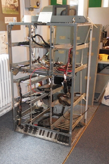
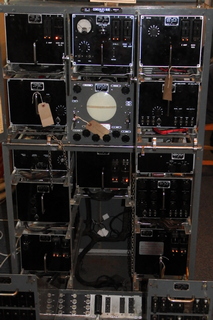
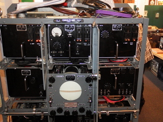
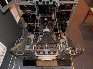
Having removed all the units from the rack, I discovered that 3 of the units had had their connectors cut off leaving me no option but to replace these. In order to replace these I needed to be able to get at the whole of the internals of the rack and so we removed the back panel and then both of the side panels. On removing the last side panel, the rack started to collapse (it had no diagonal stays, this has since been remedied). At the time, we resolved this problem by using big tie wraps - these can be see in the two photographs below. Also in these photographs can be seen the red wires that were used to replace the missing connectors to the 3 units mentioned above.
 |
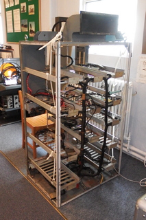 |
The three units that had had their connectors cut off were the Power Unit 872, Timbase Unit (Elevation) and the Indciator Unit (IFF) type 31. Each of these has two 12way Jones plug/socket connectors and finding out which wires went to which pins looked like being quite a hassle. However after some thought I realised that I could reduce the hassle by getting a free Jones plug and shorting all of its pins together and putting it on a socket on the end of the cables for a unit to which I knew that at least one of the cut wires went to. Using a with a buzzer and connecting one lead to the shorted plug, I could then go round the cut wires to locate those that went to that unit and labelling the relevant wires as a group, it being a simple matter later to check just which pin they went to by removing the shorting plug and checking the relevant pins. The above photos show the Jones sockets wired up for the Power Unit 872 with labels still attached and the remaining two units with wires attached to the cut ends. The Indicator Unit 31 also had its EHT connector cut and I had to rewire this too - the trailing end to the Power Unit can be seen at the bottom right of the left hand photo. Some months later, I found the cut off connectors in our store-room - it was not apparent why they had been cut off as at the time, we had assumed someone wanted the Jones plugs for something else.
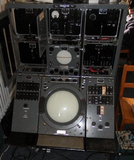
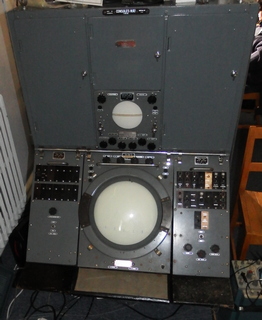
On completion of the wiring of the three units, Jim Forrester and I checked all of the connections in the rack wiring to make sure that we had what the circuit diagram said we should have. We found two wires that had been cut for no apparent reason and corrected these. When Bob had completed testing and fixing the power supplies, we put all the units in the rack in their correct places and connected up the mains. We then informed the rest of the museum staff that we were going to switch on and to be prepared for smoke, bangs, or both :-). Alf switched on and there were no bangs or smoke to our surprise, even when the HT time delay relays came in. However we had nothing on any of the CRTs. It was eventually noticed that one on the HT neons wasn't on on the Power Supply 872 (see photo below - top right unit). This supply is turned on by a thermal time delay relay which although it had worked on the bench hadn't worked in the rack. It turned out to be intermittent and a quick tap with a screwdriver handle brough it to life - it was eventually replaced.
 |
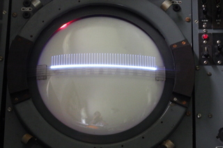 |
At this point we obtained a dot on the Indicator unit 32 (the big one) and it became obvious that we needed a trigger for the timebase unit (range). Eventually I found that the console has an internal trigger capability which can be selected on the "Sync and Blanking Panel" (third unit down on the right had side - the only unit that hadn't been removed during the rewiring). We then had a trace with nothing on it and so set about trying to get something on it and discovered that we should be able to get "Cal" markers. Having found the switch on the right hand control panel (marked "Calibration") we then had calibration markers on the screen as shown above.
From the Air Publication, it was apparent that the console in its latter days was used for Height Finding as opposed to A scan mode that we had it working in. According to the A.P., there were two links needed to be changed to get it into this mode and they were on the Indicator Unit 32. Eventually I found that these were underneath the unit and accessible by removing a plate while laying on your back. I changed these to the height finder position and we then had a partial trace. In order to get a full trace I changed several faulty components in the Elevation Timebase unit and eventually got to a point where I could make the trace "nod" by shorting the magslip output to the magslip input on the console input panel and adjusting the magslip ouput control on the timebase unit. (There's a video with audio of this here)
Now (2018) we have a nodding display which is generated in the correct manner. We had been given two magslips of the correct type but they had been stored in an outside shed and were seized up. Paul Edwards and I managed to take one of these to bits and refurbish its "innards" so that it worked correctly. Paul then made up a box using a 10rpm motor, the magslip and some of my Meccano in order to emulate the action of a nodding height finder on the magslip. This is how we now run the Console 61 in height finder mode - I added a switch on the front of the indicator unit to switch from A scan to Height finder mode without having to switch off the console and move the links over.
At this point we tried to get the Indicator Unit 31 running. This had all sorts of problems even after I'd managed to get a dot on the screen. I only had one trace and the A.P. inferred that I should have two. After much scratching of heads, we decided to test all the valves in the unit. The valve tester said that all of the valves except the CV1091 (EF50)s were OK. We took some EF50s out of the IF unit and checked those and the valve tester said they were u/s too. At this point we were doubting the valve tester and so got a brand new valve and it tested OK! We removed all the EF50s from the Console and tested them - all 23 were U/S ! We never discovered why this should be, as all the other valves were OK and they were all on the same heater chains etc. We replaced all the EF50s (CV1091) and things sprang to life - well sort of. There was a lot of fault finding went on at this stage but I can't remember just what, though my main memory is that every 100K wire wound resistor in the console was open circuit and these were replaced with modern ones (hopefully more reliable).
The IFF Timebase unit is a dreadful unit to work on (it's the 3rd unit down on the left). In order to get any of the units out to the servicing position, you have to press down a locking bar under the relevant unit and pull the unit out while holding the bar down. You need to switch the console off while doing this or you run the risk of death, and even when switched off it's easy to skin your knuckles on the components. The plugs on the units tend to catch on the locking bar and so you have to hold it down until you have the unit fully out. We eventually solved the problem of working on this unit be removing the locking bar (not required in a non-mobile system), and making up extension leads so that we could work on the unit out of the console. After a lot of work and a lot of learning about the console, we had two traces on the screen.
At this point we needed signals for the displays. For this we needed a trigger at about 20volts, Radar at 45Mhz I.F. frequency and IFF video signals. Bob Parsons set about building a "box" to generate these using inputs from Paul's radar emulator for the Console 64. Bob used the Radar Bright Up (RBU) as the timing for the trigger generator, thus synchronising the Console 61 to the Console 64. (There is a video of the Ascan with fixed targets here)Whilst he found the signal generation relatively straight forward, the biggest problem was generating noise with the signals so that they looked realistic (the opposite problem to that which normally occurs!). We now have the display running with IFF from the Console 64 on the top trace, and an A scan version of the height finder signals on the bottom trace, all of the signals being generated by Paul's emulator. (There is a video of the displays at this point here, the upper display on the top trace shows IFF from the PPI console and the bottom trace shows the Ascan version of the main display).
 |
 |
Since I took the above videos, Paul has improved things considerably and I will add another video shortly.
Unless otherwise stated, all photographs © Colin Hinson, all rights reserved.
Page last updated 26th January 2018 by Colin Hinson.