home page
| Blunham.com home page |
Radar main page |
When I left the RAF in 1974, I had been working with digital electronics for 10 years and it was with this branch of electronics that was my main interest having designed a No Break Trigger system for the RAF with Tony Mellor, and a calculator (in TTL) along with my brother. Unfortunately, Clive Sinclair beat us to producing a hand held calculator.
I joined Spectra TV as a training engineer in Bridlington (we lived in Flamborough). Spectra was TV Rental company which had displays and a desk in the local Electricity Board shops (a brilliant idea since nearly everyone came through those shops in those days to pay their electricity bills). After 2 years the company was taken over by Granada. The Granada union rep. was pleased to announce that the union had negotiated a good deal for Spectra employees. This good deal was 10% less pay! I left Spectra TV when the company became defunct.
Teletext beginnings
Thoughts about a system to allow display of pages of data started in the early 1970s. By 1972 the BBC had developed a system now known as Ceefax ("see facts") with a display format of 24 rows of 32 characters. In 1973, ITV started their system known as ORACLE (Optional Reception of Announcements by Coded Line Electronics) with a display format of 22 rows of 40 characters. Both systems used ASCII character sets and had various other things in common. Immediately the GPO announced a 1200/75 baud videotext service called Prestel. In 1973 a joint BBC/IBA/BREMA working group was set up to examine the two systems in order to recommend a common broadcasting standard. This working group came up with the October 1974 "Specification of standards for Information Transmission by digitally coded signals in the field-blanking interval of 625 line television systems". In 1975 the IBA published a description of their ORACLE service in their Engineering News.
Wireless World decoder
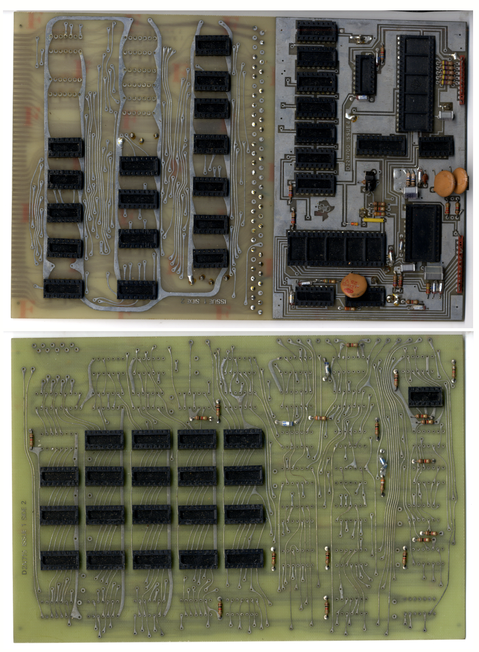
Before I left Spectra, Wireless World magazine started publishing a series of articles on how to build a teletext decoder. I managed to build one of these on my own Vero boards using mainly TTL devices from "Bi-Pak", a company that sold TTL devices that had failed test. In order to test these I built a tester using components that I had "laying around" such as DM160 indicators. When I had a working decoder I discovered that the specification that it was designed to became obsolete immediately after the last article was published. There were several new features in the September 1976 specification such as double height, held graphics etc. I set about adding these to my decoder and by the time I left Spectra I had a decoder working to the 1976 spec. The decoder was really a "rat's nest" of boards and wires and the input panel (two of the empty boards shown here), and interfaced into a GEC 2028 T.V. This was GEC's first colour TV and was a dual standard 405/625 valved set. I was somewhat wary of interfacing CMOS switches into the valved TV, but all went well. In the process of doing this, I discovered that I could use the TV as an oscilloscope by putting the digital signal into the "insert" CMOS switch input thus cutting a hole in the TV displayed video where the digital input signal went to a '1'. The main problem with this was that I couldn't display the teletext signals as they appeared in the vertical flyback interval and not the picture area. Eventually it occurred to me that if I switched the TV to a different channel to that of the decoder (which had its own tuner) then I could see the teletext so long as the two channels weren't synchronised.
I joined Marconi Radar in late 1976 as a Field Engineer working on GWS 25 (Seawolf Missile Radar and TV systems). I continued working on my decoder when I had the chance, in particular adding a feature which logged the incoming page numbers and (if told to do so) would display any incoming page with a number which hadn't been transmitted before - I never saw this on any other decoder. Marconi's decided that it would be a good idea if I went to Glasgow to work in the Yarrow's shipyards installing Seawolf on the Type 22 Frigates. I told them that Glasgow was the last place I wanted to go and that if they actually sent me I would resign. They sent me and so I resigned.
As an aside: I have never known it so cold (it was December), we had to wear 3 pairs of trousers and 2 jumpers and a Parker to keep warm on the ship and in the unheated offices. I was brought up here in Swaledale, the most northerly of the Yorkshire dales so I'd met cold before! Naval ships have watertight bulkheads that go from the bottom of the ship to the main deck. These are about half an inch thick (1.2cm). Needless to say, in order to get from one end of the ship to the other, you have to go through these which means that a hole has to be cut in the steel and then a door is fitted. I had assumed that they would use an oxy-acetylene cutter to do this, but no, they used a pneumatic chisel! It was impossible to shout to someone 12 feet away in an enclosed cabin to do wiring checks when they were doing this at the other end of the ship. Strangely, the men using the chisels were deaf!
While I was working out my notice an advert for a job in teletext design with Texas Instruments in Bedford appeared on one of the teletext pages being transmitted by ITV and so I applied for the job. I was interviewed by (the late) Kailash Pandey and Bob Parsons (who I still work with at RAF Henlow Signals Museum). I had to explain how the decoder that I had built worked, in particular the new features from the new 1976 spec. that I had added (I found out later why I was asked about these). I got the job and started work for TI in February 1978. We moved from Flamborough to Blunham in the following May and have been here ever since. There is only one Blunham in the world, so it's easy to find on the web.
XM11 decoder (and Viewdata board)
What I found amazing when I joined TI was the instant communication around the world within TI by email. To use this you used a 914 terminal to send and a printer to receive. The 914 terminal was a 14" CRT and used a 1k core store to hold the page of text, the printer was usually a "Silent 700" thermal printer. Each printer had a "name", the two I remember were "EBAT" and "BRTC" and so long as you knew the terminal name you wanted to send to, you could send to any TI department in the world - instantly, as with todays Internet email. Whilst we had T.I.990 computers in Bedford, we could also use the "big" 1Mb memory machine in Dallas to run big jobs. You just had to be careful that any print-out was directed to Bedford and not Dallas (which happened regularly!). The communication was by satellite.
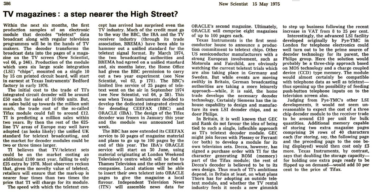
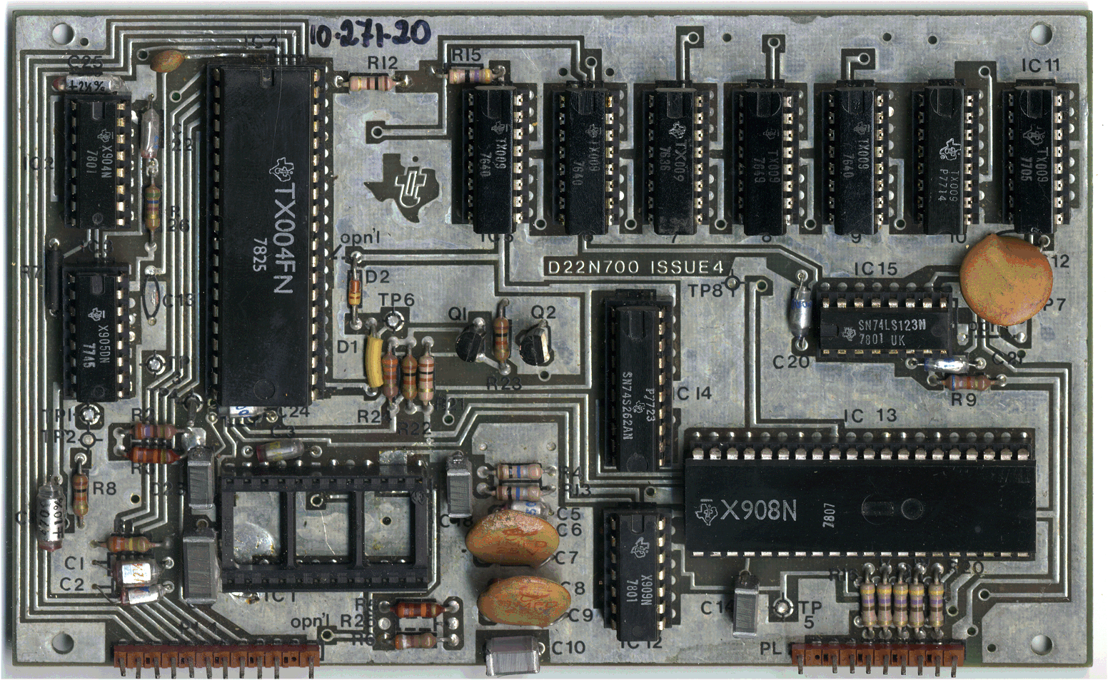
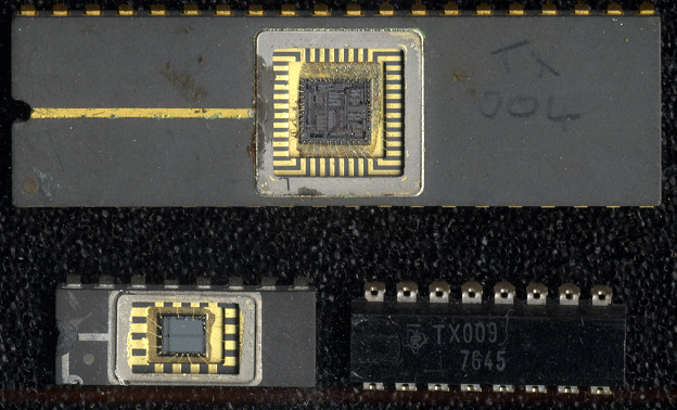
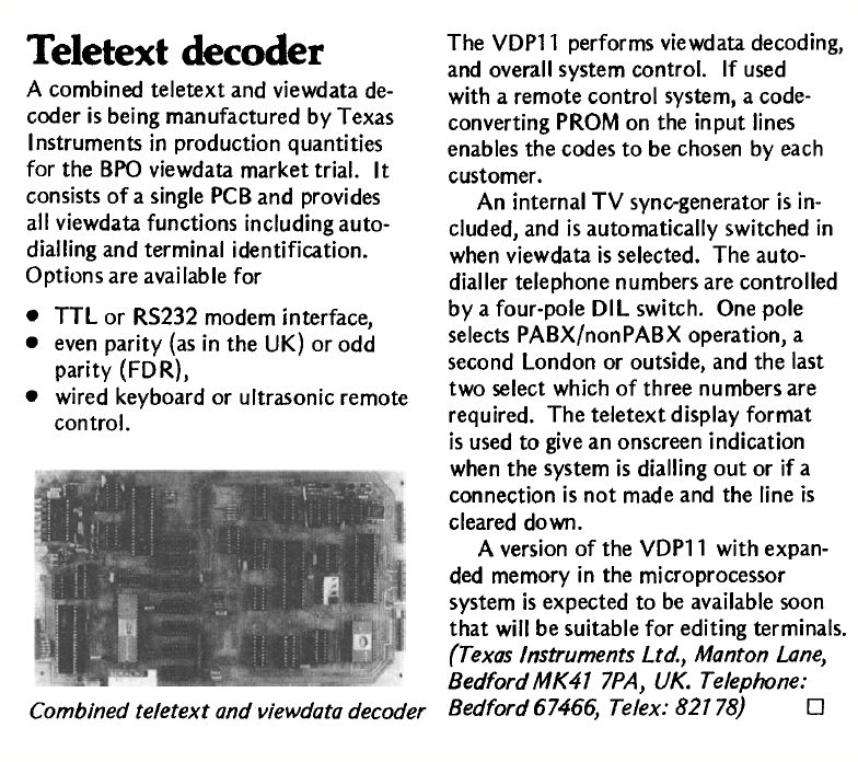
When I joined TI they had a decoder in production. This was the "Tifax" XM11 which was designed to the above 1974 specification and so lacked the later 1976 features. The XM11 was the first mass produced teletext decoder in the world but I can't get an exact date for it's release. The IBA document mentioned above mentions a press release for Tifax dated May 1975 and this New Scientist page mentions the same date. TI produced an application note for the XM11 decoder and there's also some information about it in this book. Here is a photograph of the XM11, along with a photograph of the XM11 IC's (apart from the TX005 data slicer).
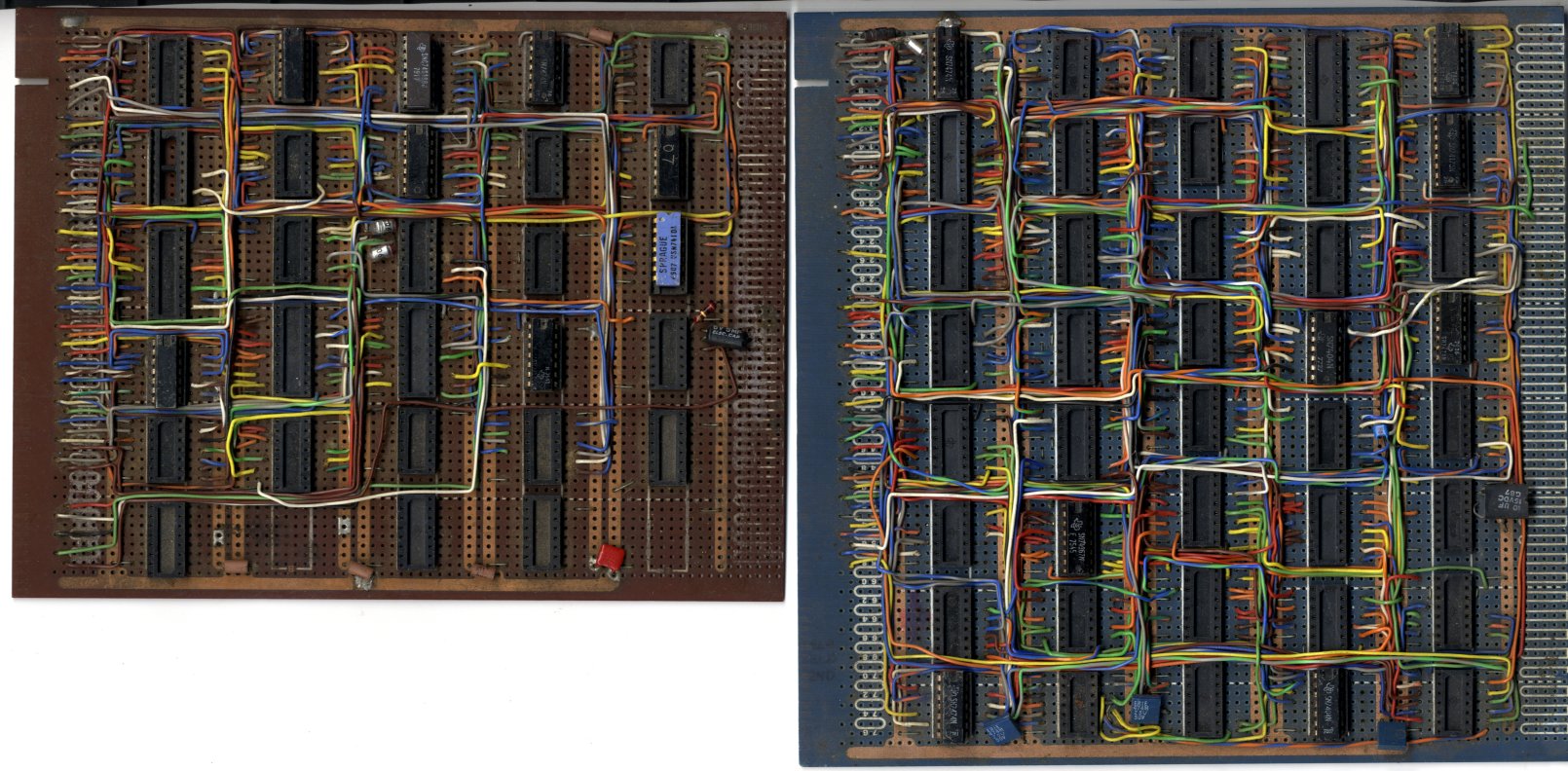
Robert Nokes developed the XM11 viewdata board and provided me with this article and photo. I have two boards that were obviously from the XM11 viewdata, Robert thinks that they may have been Dennis Spicer's XM11 data interface development boards, so until someone tells me different, that's what they are.
XM12 decoder
The decoder that was in design as I started with TI was the XM12 and this was designed to the 1976 specification. The GPO went along with the display format of the 1976 spec. for their Prestel system.
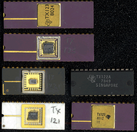
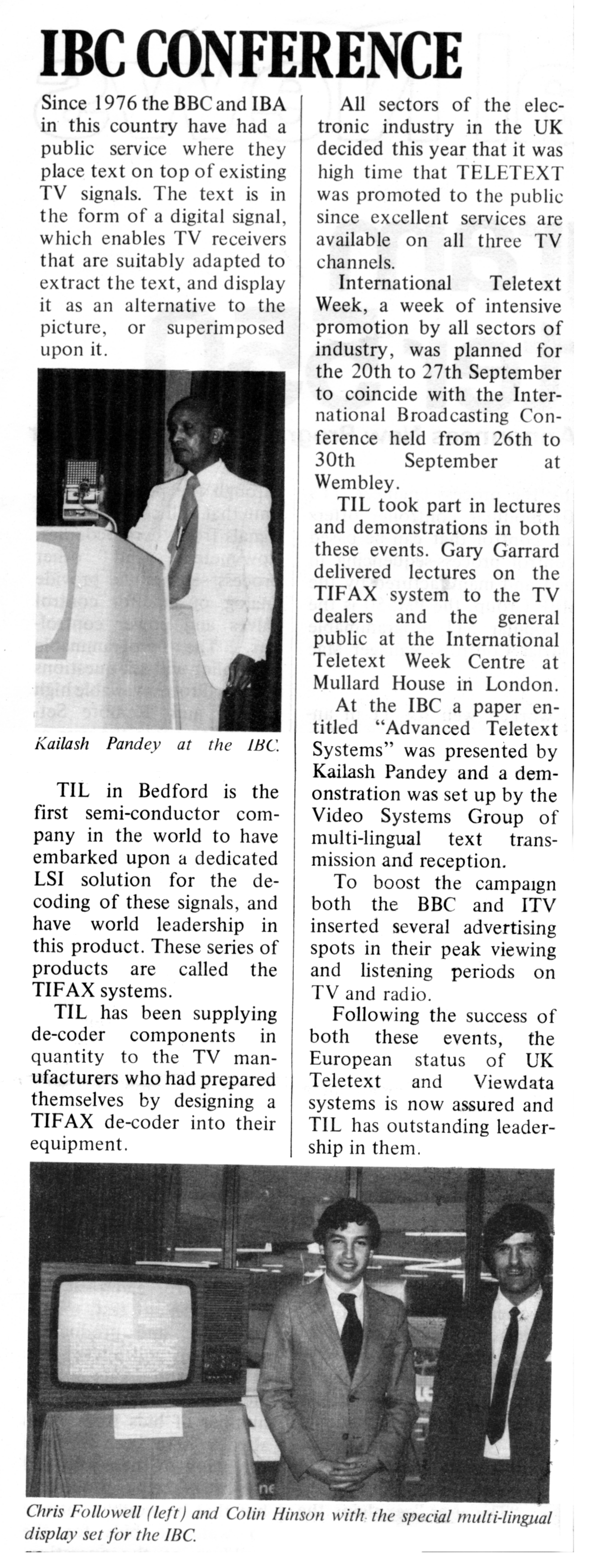
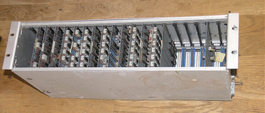
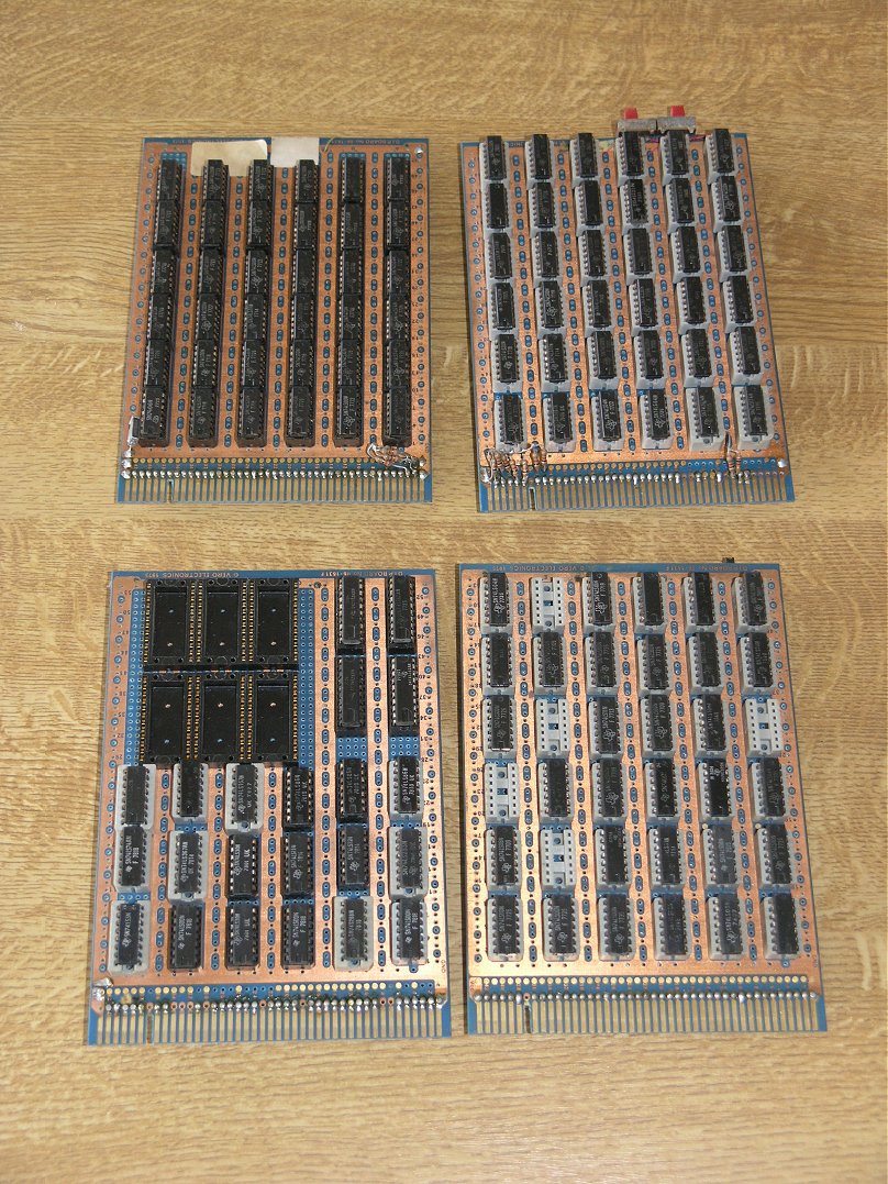
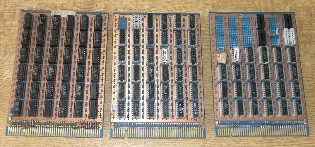
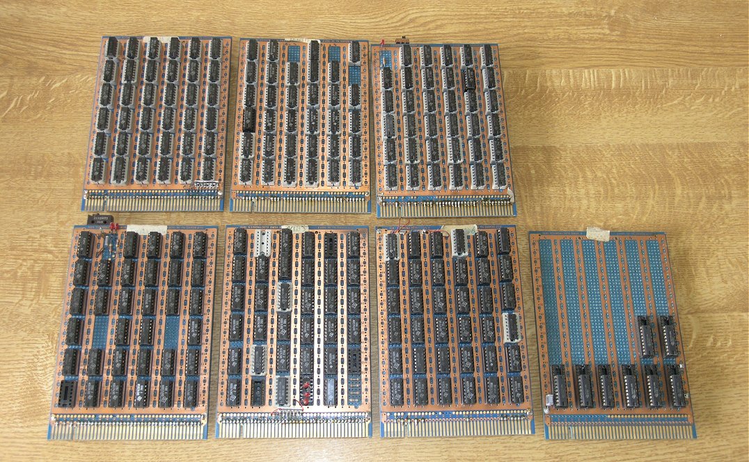
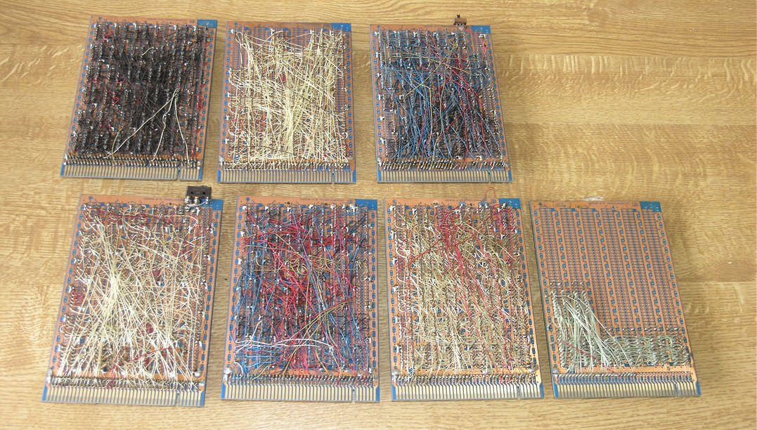
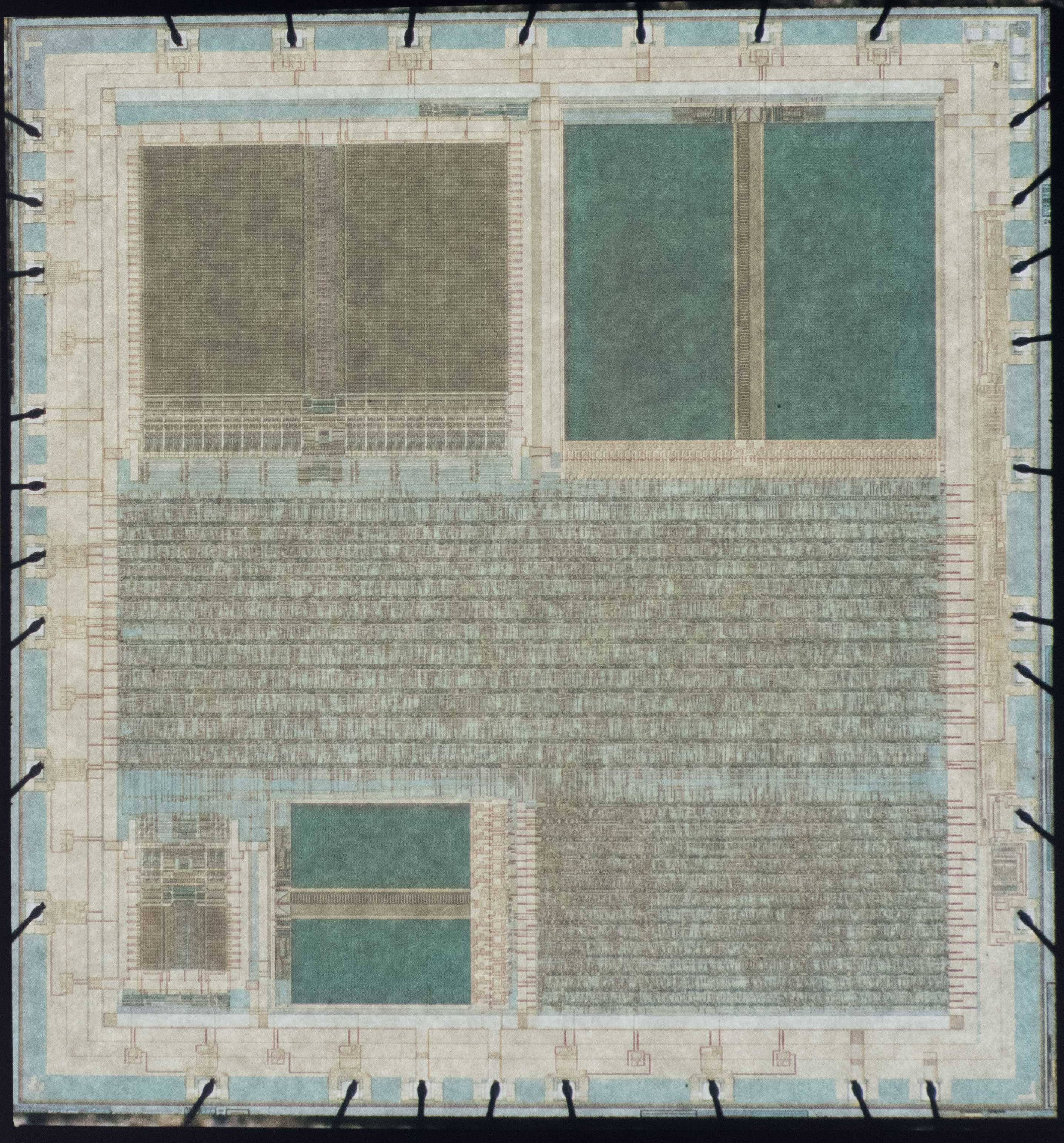
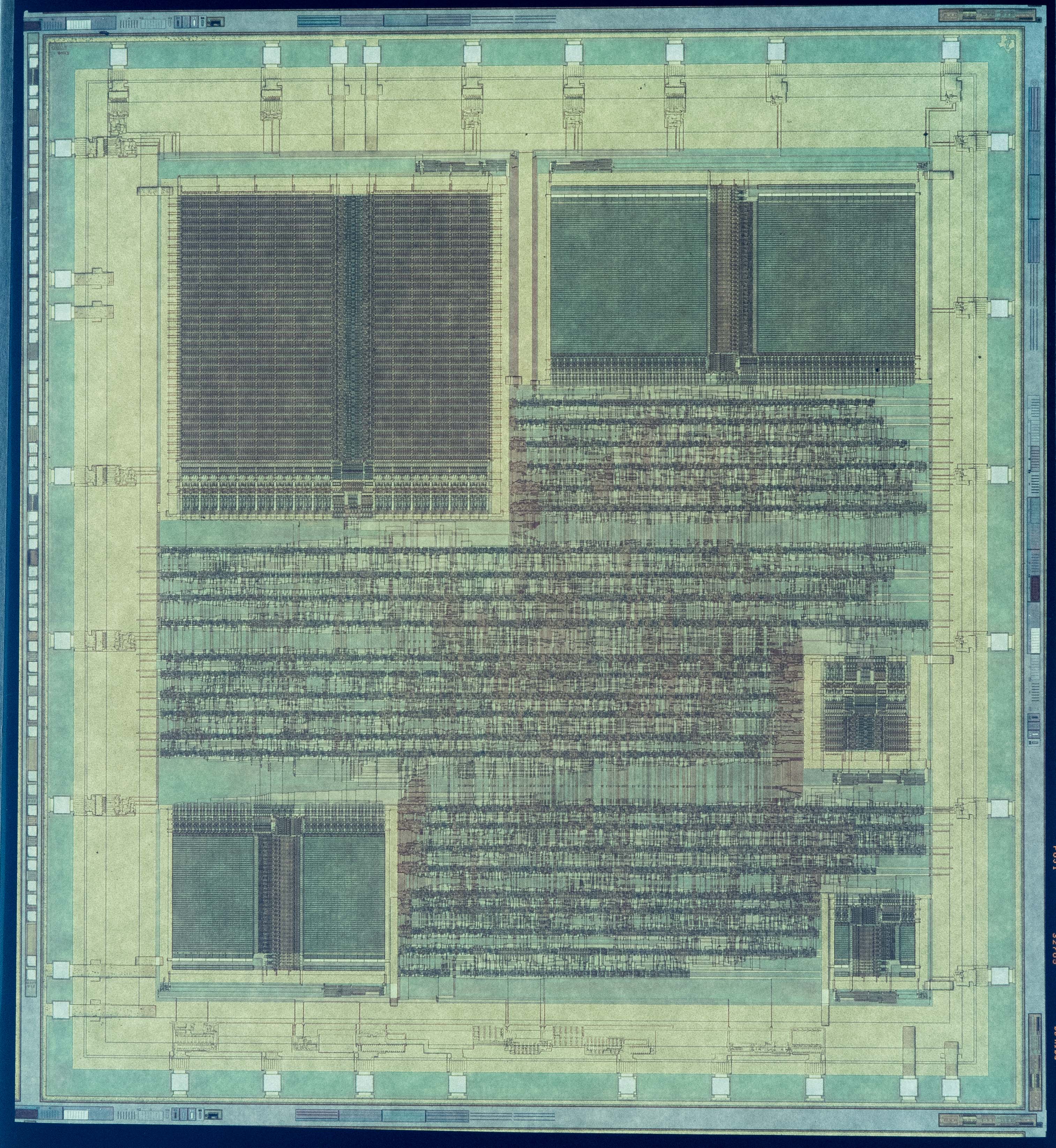
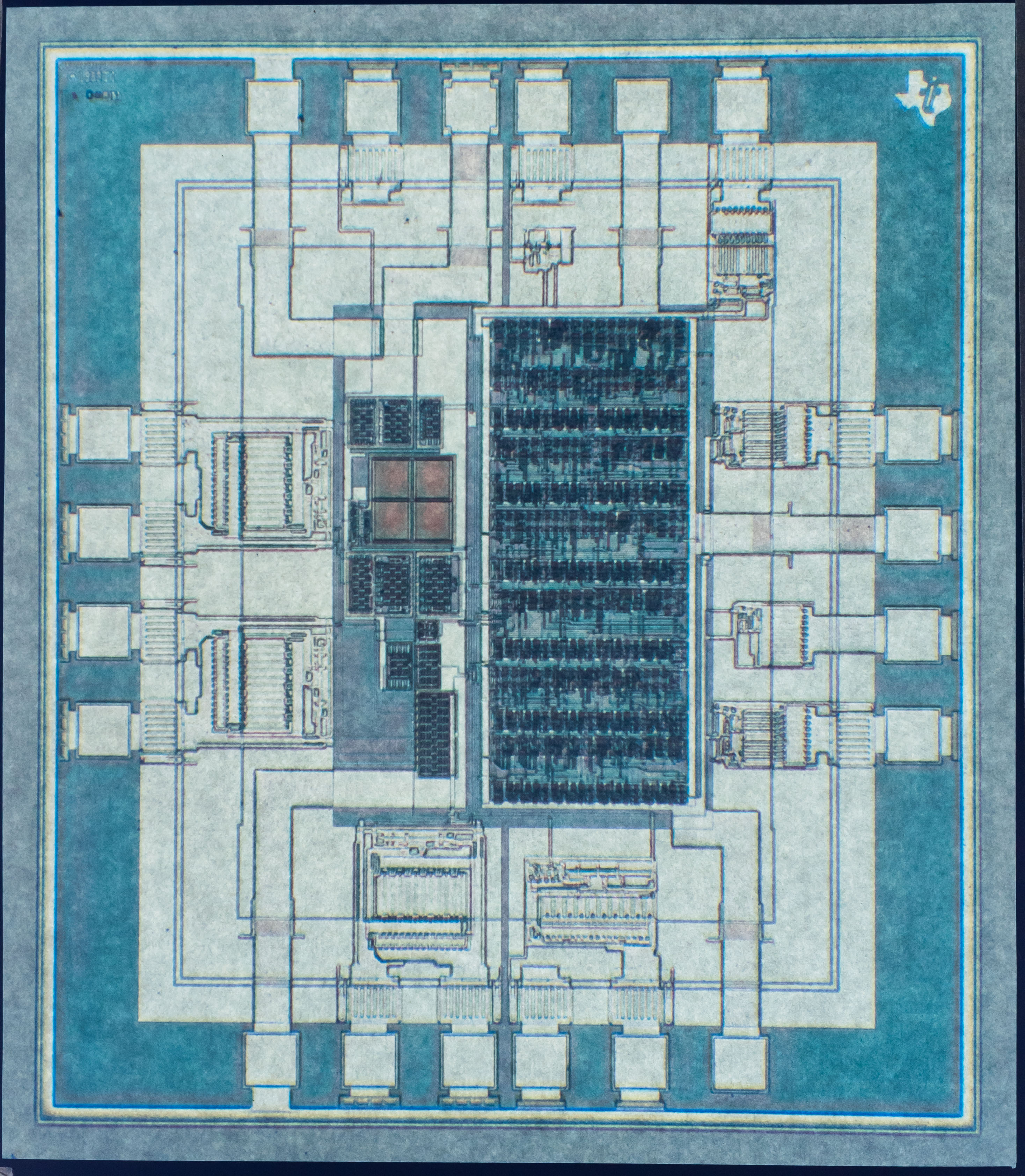
My job for the first 6 months was to debug the wire-wrap boards in a Vero rack which made up the circuit of the proposed Integrated Circuits (IC's), namely the TX121 display, TX122 waveform generator and TX123 teletext receiver - these are shown here. Additionally there was a remote control chip TX126 (Alan Sinclair doing the design and Jon Hudson doing the layout). Kailash Pandey was the manager, with Bob Parsons and Peter Vinson as the designers, along with various others (Gunner du Gunderson, Clive Pill......). Jon Hudson tells me that he worked on the layout of the TX124 which was "an XM12 interface to something". My wife Pauline found a news clipping containing a photograph of Kailash taken at the IBC Conference in 1978, along with Chris Followell, myself and the XM12 demonstration. The chips were designed to be produced in I2L (Integrated Injection Logic - there's an article about I2L at the end of this book), which seemed like a good idea at the time. Eventually we had 3 "bread-boards" (Vero racks) up and running after much work by Aubrey Graham, the wire wrap expert. Having proved the design, it was sent to mask in Dallas. I went to Dallas in November 1978 along with one of the racks in order to be able to check the TX123 chips that were due to be available as I got there (they needed the rack to supply the relevant waveforms to the TX123).
As an "aside", the second day of my visit to Dallas I went out from the hotel where I was staying to my car and couldn't get in due to there being half a inch of ice all over it. During the night there had been an ice storm where warm air goes over freezing air and then rains through it - the rain turning to ice when it hits anything. When I finally got into the car, I had to take the Expressway to TI - that was interesting to say the least, cars at all angles on the ice!
On my return to the UK after successfully checking the TX123, my first job was to build a teletext page generator. I used EPROMS to hold the page data. It could transmit up to 16 different pages with the rows being transmitted in any order (after the header row of course). This proved to be invaluable in testing obscure page data sequences.
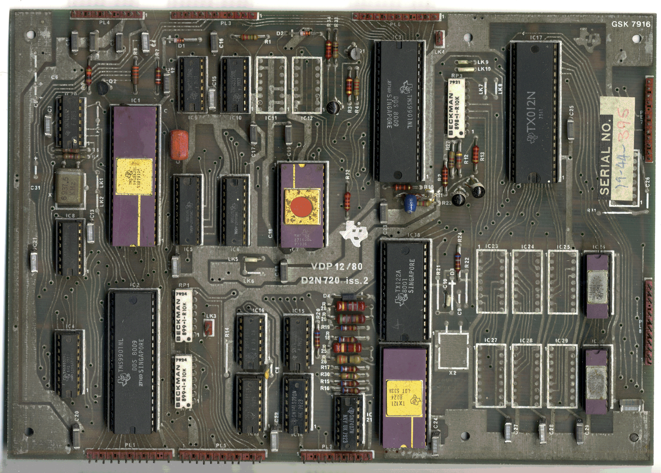
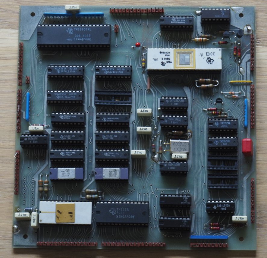
In addition to the Teletext decoder there was an associated Viewdata board, the VDP 12/80 which I never worked on. Robert Nokes did the development for this using a TMS9980 microprocessor with non-volatile RAM for user-defined parameter storage, e.g. phone numbers. The only choice for this at the time was to use TI's DIFMOS (Double Injection Floating-gate Metal Oxide Semiconductor) TMS3529, this became known (particularly by Robert) as DUFMOS, due to its initial manufacturing problems. I sent Robert a photograph given to me by Colin Davies and asked him what it was. His reply was: "Good heavens - all the ghosts are reappearing! Well, after VDP12/80, there were two abortive attempts at cost reduction, then TI finally called it a day. The first replaced the TMS9980 subsystem with TMS9940, which had a prototyping (EEPROM) variant. The TX012 was replaced by discrete logic. This board (XM12/TMS9940) is what you can see in Colin D’s photo. Next, the TMS1000-based solution. Processor dead cheap, a pig to program but could (just) do the job. No solution though to the high cost of project12’s I2L technology. "
Photographs: The Vero rack containing the wire wrap TTL boards. The wire wrap boards for the TX121, TX122, TX123 and showing the wire wrap side for the TX123. The 3 final digital devices: TX121,TX122,TX123, with their lids on and off. I don't have a TX124 or TX126, so no photos.
Data slicers. These were always problematic! The data slicer for the XM11 was the TX005, and for the XM12 it was the TX014. Frank Fattori did the design for the TX014 and Jon Hudson and Clive Pill worked on the layout. Frank later said that the revision letters should have started at Z and worked back then the production devices would have had lower letters! There's more on data slicers below.
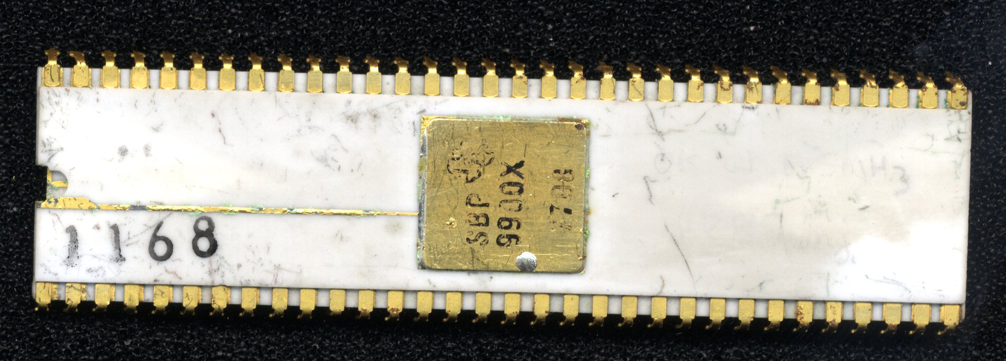
We had a printed circuit board designed that was (to the outside world) backwards compatible with the XM11 and successfully got some of these working. The company was gearing up to go into mass production when a hold was put on our devices going through the front end ("fab"). This was due to problems with the production of the military spec. microprocessor SBP9900 - and the advanced version, the SBP9989 (data book). This processor was a lot less susceptible than MOS to Electro Magnetic Pulses (EMP) and so was important. These problems were never really resolved and production of the processors always took up the whole of the allocation and so we never got any more devices through. TI Bedford decided to get out of Teletext and so the team had to find other things to do. Ironically, one of the "sideways" jobs I did later was to assist Dave Cutler with the support of the SBP9989.
Up to the early 1980s, I worked on Digital Video (Pete Nicholson), SLIC (telephone Subscriber Line Interface Circuit) - Trevor Jones (my apprentice?) and I told them it would never work and they eventually pulled the plug on the device. I designed a lightning generator for testing voltage suppressors on telephone lines for the Power Group (mainly Mick Maytum and Rod? Rodriguez). I was used to using Thyratrons on radar, however these used heaters and I didn't really want to have to use more voltages. In the end I spoke to the English Electric Valve Company in Lincoln who recommended an ignitron (mercury vapour with a pool of mercury in the bottom of the valve, ignited by a wick dipped into the mercury creating a spark). The ignitron was capable of a rise time of 30,000 amps per microsecond and created a nice Electro-Magnetic Pulse (EMP) which demolished the triac on test before the volts got to it ! The voltage was adjustable up to 10kV and the pulse length determined by the size of the capacitor(s). This was still in use when I left TI in 1998.
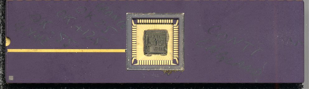
Somewhere in this time we moved labs, and in the new lab my manager was Raj Gunawardana. Raj was the speech synthesis expert and knew nothing about teletext or Viewdata, but in his travels came across a company called Phosphor Products Co. Ltd of Poole which produced large flat screen phosphor panels and were interested in producing a Viewdata unit. I spent about 6 months working on this in conjunction with Simon Bliss (Phosphor Products). I used Mullard's Lucy chip as the telephone data interface and a TMS9995 to do the processing and the screen display as it needed a fast processor to keep up with the screen refresh requirements.
Antiope and TMS3556
In France in the late 1970's a project called "Minitel" was being developed. Minitel was a service similar to Viewdata and was the most successful on-line service prior to the World Wide Web. The chips for this were developed by Thomson (French of course). At the same time a teletext service was being developed in France. This was called Antiope. The display system was similar if not the same as that used for Minitel and considerably more complex than teletext (Minitel was finally dispensed with in 2012). Texas Instruments France (TIF) started development of a display chip, the TMS3556 (data book) for this and Minitel (but I seem to recall were locked out of the Minitel market). The way they went about Antiope was to have a data slicer that fed the incoming data to a serial to parallel converter/framing code detector (prefix processor) which dumped the data byte by byte into DRAM (Dynamic Random Access Memory) through the display chip (TMS3556). This DRAM also held the display data and character set. A microprocessor was required to process the teletext data buffer in the DRAM and turn it into display format. Of course it had to retrieve the data through the display chip and write it back to the display chip as displayable data. Antiope was eventually dropped in favour of WST (World System Teletext) in 1991.
TMS7000
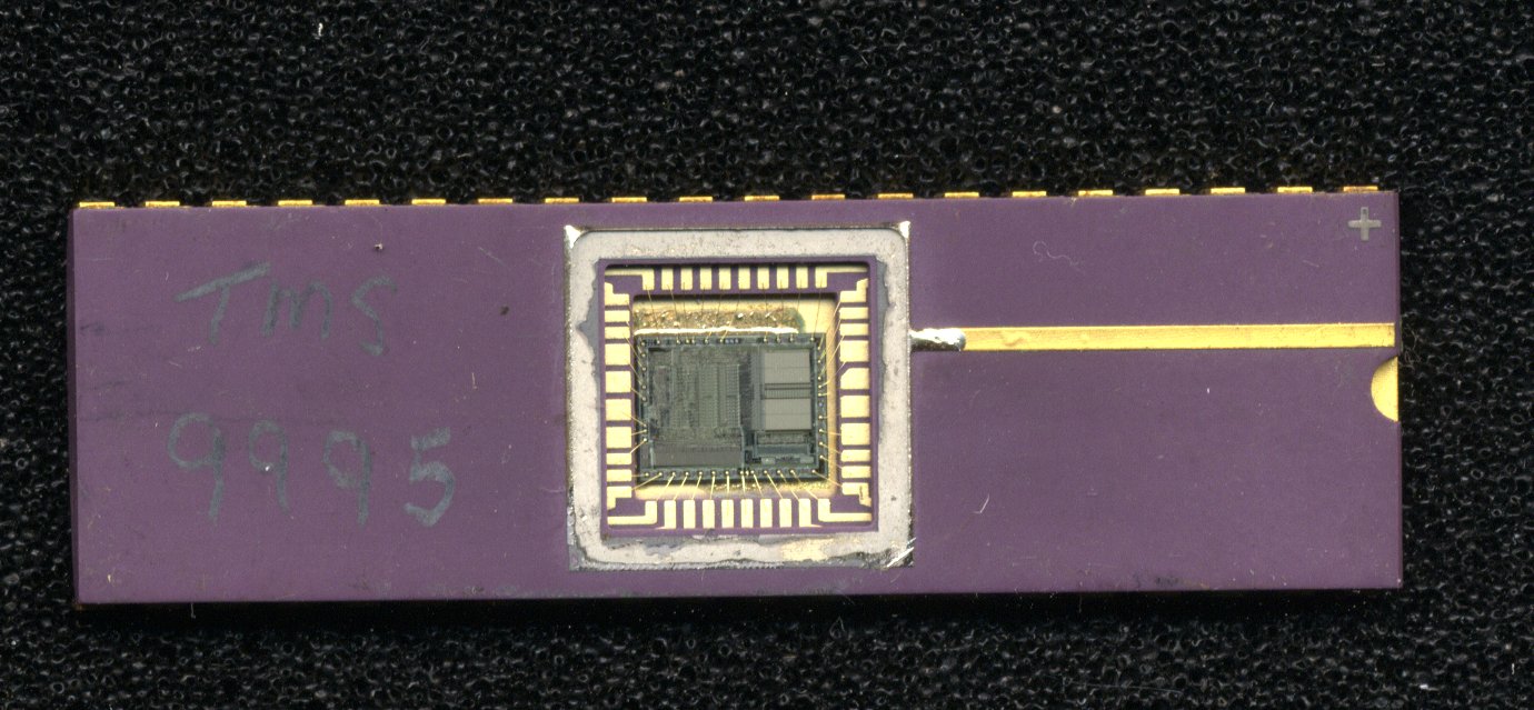
It became apparent to those at TIF that there was a use for this system as a teletext decoder for the European market and one day Rob Matthews from TIF arrived at TI Bedford looking for people with teletext knowledge. As Trevor Jones and I had just finished with SLIC, we were chosen to have a look at using the French chip set in a teletext decoder. I went to France to get an introduction to the chip set, and we came to the conclusion that it would do teletext, but the Prefix Processor (or Packet Identifier) would need to be changed. This was designed and came back as a TMS3551 (Data book). I was then asked if I would go to France for 10 weeks to write the code required for teletext in TMS7000 assembler. I agreed to this (even though I'd no idea what TMS7000 assembler looked like, though I was more than familiar with TMS9900 assembler). My family and I went to live in Cannes sur Mer (about 5 miles west of Nice) and I worked in TI France (at Villeneuve Loubet). At the end of the 10 weeks I had a working decoder - well at least it worked off the VG (Vacuum Generators) teletext generator. We also gained a good knowledge of the scenery and beaches around the area - Nice, Cannes,
UK development for TMS3556
On my return to TI Bedford and running the decoder and software I had, it was obvious that there was still a lot to be done to make this a marketable decoder and so Trevor and I set about doing this, it took several months. At some point in this period, Colin Davies came into our lives as the teletext (and Nicam stereo) group manager - as the only two people called Colin in the building, this caused quite a lot of confusion! The main advantage of the French system was that it had more than one page store. The TMS3556 was capable of a much more sophisticated display than teletext required as it used an attribute byte with each character byte, the problem with this was that the teletext data had to be processed to determine which attribute to apply to each character and so we couldn't simply dump the incoming data into display RAM. Since the TMS3556 needed a buffer store and display store as well as page storage, the minimum DRAM it could use was 8Kbytes. This gave 4 to 6 pages of page store which allowed capture of the pages indicated on row 24 and so instant access to these. Most of the competition decoders at the time were only capable of a single page storage. We sold these decoders into several of the South Wales TV manufacturing companies.
Instant Text
While waiting for the masked TMS7000 microcomputer to come back from the front end I was asked if I could do something for the IERE conference in 1984. I decided that I would try to design a decoder capable of capturing the whole of a teletext transmission including sub-pages. On asking the BBC and ITV teletext people, this seemed to be around 800 pages, ignoring those that were time coded. To do what I wanted to do therefore required about a megabyte of ram (expensive! - but TI made DRAM). As the TMS3556 was incapable of controlling this much DRAM, I decided to use a TMS4500 DRAM controller driven by a TMS9995 microprocessor. This processor is 16bit and fast for its day and uses the same instruction set as the TMS9900. We had an XDS for this device (a plug in emulator that allowed breakpoints to be set and data to be read out). I wrote the software for this in about 2 months - it was incredibly complex, having to get the incoming data from the TMS3556 data buffer and decide where to store it, and maintain a link table so that it could remember where it had put it and then when asked to do so, do the translation from the data in the page store to the TMS3556 display data. This decoder could store up to 1000 pages, the circuit diagram is here, and the source listing is here.
I'm pleased to say that the effect on people who had used a standard decoder was dramatic when they came to use this, as the display really was instantly there after you typed in a page number, pressed a backwards or forwards key, or used one of the coloured buttons to access the linked pages on row 24. I presented my paper at the IERE conference and it was well received.
I wrote the software so that I could send the data from captured pages down the RS232 connection to a PC and so store them. The output gave all the data required to retransmit the pages - i.e. row and magazine as well as the displayed data. If you want to use what I have, then you can access the Sky One pages (zipped) Magazine 1, Magazine 2, Magazine 5 and Magazine 8. Be aware that some of these are not perfect due to reception errors - spaces due to parity errors, spurious characters due to noise etc.
Here is a photograph of a display produced by this board, note the sub-page number in the header. The board could display row 24 in either normal or inverted colour mode. In inverted colour mode I took advantage of the parallel attribute capability and started the background colour at the start of the row - impossible with teletext as the character colour has be set before the background colour can be set, and this takes a character space.
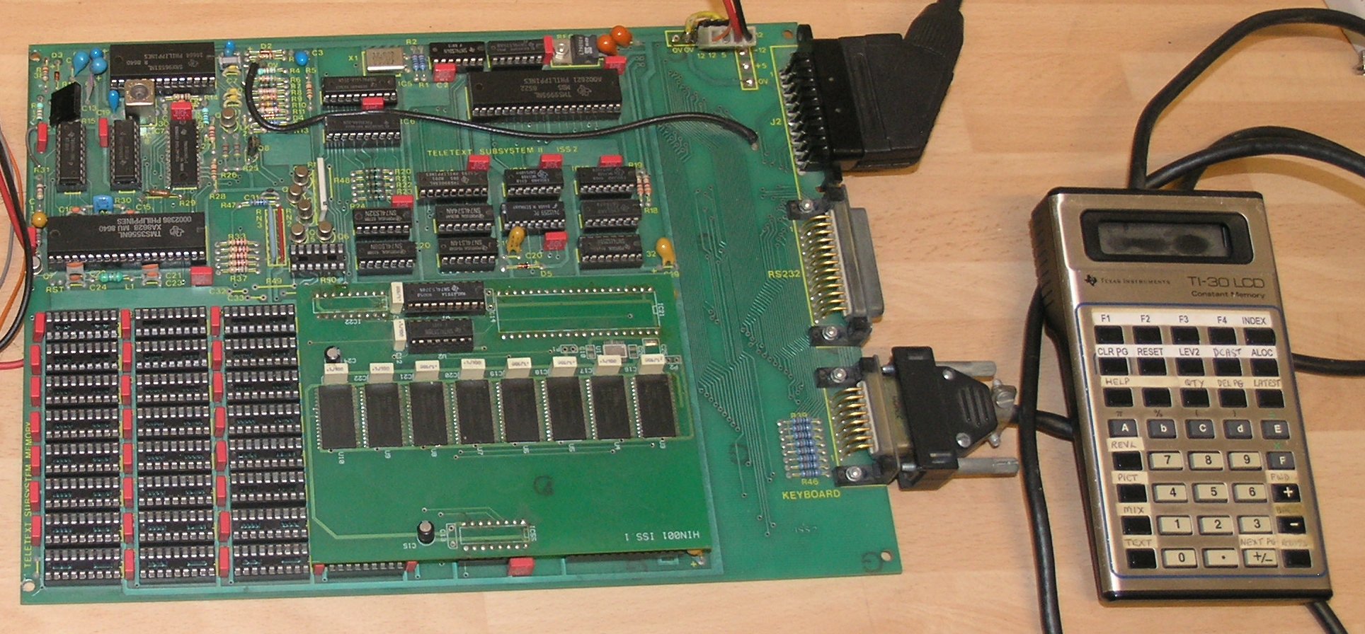
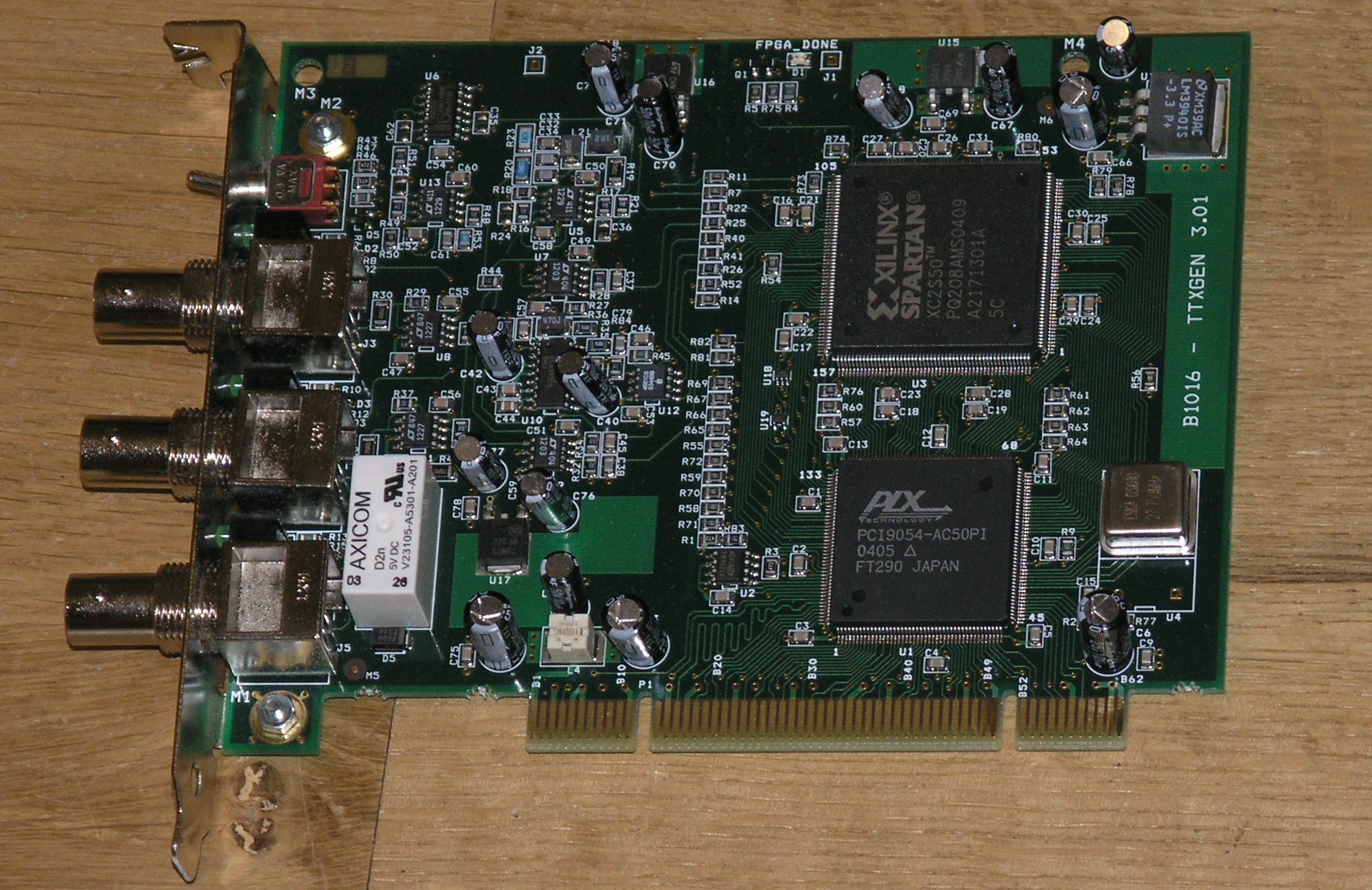
Several years later after I had left TI, I was asked by Robert Owen (ex TI) if I could generate two of these boards for a radio station near Knebworth. These were to be used by the presenters to keep up with the news, racing and football results etc. They had a few special requirements not the least of which was to be able to store up to 4000 pages (the output, particularly of ITV had increased considerably). I designed a board that would plug on to the "Instant Text board" and take the signals from the DRAM controller socket in such a way as to be able to take 4Mbytes of static RAM. Richard Miles generated these from the schematics and I managed to get the software running and delivered the boards on schedule. They were delighted. There is a photograph of this board here, along with its TI30 keypad.
Singapore Teleview
The Teleview system was essentially similar to Prestel, but only used the phone line for the user to talk to the computer, the output of the computer was via full field teletext transmission using daisychained inserters to cover the field in blocks. The work on these and coordination within the EASAMS Teleview Team was done mainly by the late Mr. Norman White - director for VG Electronics the teletext Inserter Provider.
Teletext Geometric Graphic drawings and Photographic Displays where not part of the teletext standard but by use of the designation code utilised the rows for data packet transmission with Ack/ Nak returned via the telephone modem (as per Prestel ). The actual protocols were derived from work at BT Martlesham ( Dr Anthony Harris and Graham Hudson) and the Prestel Development Dept. formally led by the late Sam Fedida.
The video display graphics were based upon a Motorola 68000 microprocessor as graphics engine and TI Video RAM (which had built in shift registers).
TI was asked in 1987 by EASAMS (Marconi) of Fleet in Hampshire if they (I) would assist with this project. They needed someone with Teletext knowledge to design and program a teletext front end and microprocessor to receive full field teletext (i.e. a teletext transmission with data on each line of the normal picture). TI were the only company producing chips that were capable of full field and had programmable framing code devices hence EASAMS reason for asking. I used the French devices for the reception and the TMS3551 as the "front end" (serial to parallel converter) as this allowed me to buffer the incoming data in order to inspect it for the required packets. The TMS7000 microcomputer was chosen as the processor to do all the work for this. It had to interface with the 68000 which was doing the display and other work. I was somewhat disappointed with the time that the 68000 took to respond to an interrupt request (compared to the much faster response of a much slower TMS9900), but found a way round the problem in the end. This job took several months and I never got to go to Singapore on that occasion.
There's some information on the Internet which was added to by Paul Wonnacott (EASAMS lead engineer for the terminal, modem and keyboard functions).
https://en.wikipedia.org/wiki/Internet_in_Singapore
Channel 4 IDENT
I don't know if it's still the same, but in the 1980s, Channel 4 TV output was all recorded apart from horse racing. This meant that the whole of the country went to adverts and came out of adverts at the same time. In order to achieve this it had been decided to use teletext and so a method of using teletext had to be invented. One of the people at the above mentioned IERE conference had seen my presentation and TI was contacted to see if there was any chance they would be interested in developing the software required to do what they wanted to do. TI's answer was 'no', but they suggested that I might like to do this in my own time. I agreed to do this, and in conjunction with Ellis Griffiths (Chief Engineer) of Channel 4, we agreed to develop this system known as IDENT.
One day on arriving home from work, there were two large parcels waiting for me. On unpacking these I found an Amstrad 1512 PC and a monitor - no note, nothing to say where it had come from. It was the top of the range machine in that it had 2 x 5¼" floppy drives and a 10Mbyte hard drive. Later that evening I got a phone call from Ellis and all was explained. Some days later a nice 14" Hitachi TV arrived.
Clearly it wasn't a good idea to transmit the required data in plain teletext and so an encryption algorithm was generated (by a professor somewhere) and the framing code was changed so that normal decoders wouldn't respond to the packets.
Along with needing to be able to cue video recorders, there was also a need to transmit the programming schedule for the next 30 days and then to print it at the receiving end. This meant that if we used the "Instant Text" board design, we could store the whole of this in the DRAM on board along with everything else required to meet the specification.
Ellis had printed circuit boards made, one for the decoder and one for the DRAM. These boards were designed by Richard Miles who TI later also used. He produced some amazing boards for us. The pcb's went into a small Vero rack along with other boards that were required such as interfaces to video recorders and printers.
On completion of this project I was asked to get 10 Instant text boards made (we only had one and that was the prototype bread-board). With Ellis's permission we had a single board made by Richard Miles. He made a single board with what would have been the back plane at the end using the design for the decoder and the DRAM boards - these are the boards you see the photographs of in the above paragraphs on Instant Text.
While I had been dealing with the Instant Text boards, Trevor had been looking at doing Viewdata with the TMS3556 and while he had some good ideas, TI management didn't want to go down this path. At this point there was a re-organisation and we moved out of "the pipe space" where we had been to having desks in a light and airy room overlooking the inner quadrangle and a lab in a better position at the opposite side of the building.
Unitext
After the move, Trevor suggested that we might look at doing teletext in real time using a RISC processor of our own design. We put the idea to Colin Davies and Pete Nicholson (our department manager) and they agreed to give us some time to have a go at doing this. We set about the task, Trevor started on the design of the processor while I started design on the front end and the display. It soon became apparent that we needed the equivalent of an XDS for this job, and so I designed a board using the TMS995 and TMS3556 that would allow us to see the various parts of the RISC processor on a TV display (there's a block diagram of the RISC processor here so you can see what the TV screen is showing you). This Control board used two euro-connectors to connect into Trevor's board. It very quickly became apparent that writing micro-code in machine code (hex) format with a 56bit word wasn't a good idea, so Trevor set about generating an instruction set for an assembler and I set about writing an assembler to run on our 990/12 computer. In the middle of the Unitext development it was decided that we should start using PC's instead of the 990/12. This meant that we had to copy all of our data across onto PC's. Whilst the 990/12 had floppy discs, they were of the 8" variety and we didn't have a PC system that could manage these and so we copied everything across by RS232 - it took a while!
The 990/12 computer was effectively a big mini-computer and could deal with up to (I think) 24 users. It had tape drives, Winchester discs and small Winchester drives. For its day it was a really nice machine to work with. The instruction set was as per the TMS9900 with a whole load of additions. When we stopped using this machine, the whole thing was sold at a very cheap price to Richard Blanden (a B.A. pilot). Richard died some time ago and his wife presented the computer to the Cambridge computer museum (Centre for Computing History) where it now resides. There's a detailed description on Wikipedia
The net result of losing the 990/12 was that we lost the 9900 processor tools - the 9900 assembler and the micro-code assembler that I had written. I experimented with various languages that had compilers for MSDOS, such as Fortran, Turbo Pascal, and Turbo C. I eventually used Turbo C (and later Turbo C++ and C++) from Borland as the output was fast and it had a good capability for manipulating large arrays and the PC ports. I re-wrote the micro-code assembler and the various other software tools that were required for the project, all in "C". There is an output from my assembler for the code that ran on the Control board here in text format. I can't find any micro-code for Unitext, but you will find listing output from my assembler for the later Eurotext here in text format.
I managed to get the micro-code assembler running so that Trevor could use it to program up the RISC processor after solving one or two communication issues! I should explain at this point the difference between micro-code, machine code, assembler and high level languages such as Basic and "C" etc.
The boards we used for the prototyping were wire-wrapped by Trevor and I. We had major problems with earth loops and had nearly the whole of the department trying to fix the problem. These were eventually fixed by joining all the earths together before they went through the connectors on both sets of boards.
Unitext was to run at 11Mhz - fast for what was then the current technology (2 micron). This meant that our breadboard prototype also had to run at 11Mhz. It was not an easy task to design a large board in wire-wrap that could do this. Trevor got on with designing the circuitry for this while Peter Vinson of the ASIC group designed the Video Display Processor (VDP) for it. Bob Parsons got started on the data slicer and I got on with writing the software for the for the control of the "emulator" board. Once we had a working system, it was decided to convert the circuitry that Trevor had designed into a set of ASIC gate arrays that we could put on a pcb along with Peter's VDP. This was done using several 72 pin flat pack ICs, thus giving us a system more representative of what the final chip would do. Another advantage was that we could use the 2-phase clock system that was needed on the final chip. The ASIC gate arrays were produced using Bedford’s rapid prototyping e-beam facility.
The system involved two boards, the control board (the board with the TMS9995 processor) and the chip emulator board (photo from Colin Davies). The control board could single step the micro-code, run it at a relatively slow clock speed or let it run at full speed. On the control board were fast RAMs into which the microcode was loaded and on the chip emulator board there were sockets that could take fast EPROM's which could be either selected by the control board or, if the control board was disconnected, allow the chip emulator board to run at full speed as a stand-alone teletext decoder. The control board had teletext pages programmed into its processor's code which it could feed into the front end instead of live teletext, thus allowing single step de-bug of the teletext receiving micro-code. The micro-code was downloaded into the TMS9995's RAM from the PC after assembly which the emulator board could access.
The RISC processor had to process the incoming teletext data in real time. The clock speed of this was 6.9375Mhz, which gave a data rate of about 1 byte per microsecond. A clock speed of 11Mhz allows just over 10 clock cycles per microsecond and so it was necessary to process an incoming teletext byte (of any type) in 10 instructions of the processor. Clearly it was not possible to decode 4 bit Hamming encoded bytes and then deal with them in 10 clock cycles and so I designed the front end circuitry so that it presented the processor with Hamming decoded bytes, parity checked bytes and 8 bit data through a multiplexer so that the processor could select what it needed at any given point in the teletext row.
A teletext row (see pages 14 and 15 of the 1976 spec.) consists of 2 bytes of clock run-in followed by a framing code (the front end hardware takes care of these). These are followed by 2 Hamming encoded bytes containing the magazine (page hundreds) and row address, then 40 bytes of page data for each of the rows 1 to 23. Row 0 (the header row) contains 8 more Hamming encoded bytes, the first two of which give the page tens and page units, these are followed by 4 bytes for the sub page number and 2 bytes for the page mode/instructions (newsflash, clear page etc.), then a further 32 bytes for display, the last 8 of which normally give the current time.
In order to be able to control the device as a user, it needed some form of interface to the TV remote control via the TV's microcomputer. The obvious system to use was an I2C (Inter Integrated Circuit) bus as TVs use this to control all the systems within the TV. I had previously designed an I2C interface and it was included in one of the flat packs on the emulator board. The control board had a keyboard with which to simulate a remote control so that page numbers etc. could be input and presented to the RISC processor as if it was coming in on the I2C bus so that it knew which page it needed to capture. In order to capture a page, it needed to look for the correct magazine (page hundreds) and row 0 (the header row), if it found these correct then it needed to compare the incoming page tens and page units with the requested page number and if found, start putting the data bytes following into the display RAM for the VDP to display on the TV screen. To do this, it needed to calculate where to put each byte and this was one of the hardest problems to solve. The RAM was linearly addressed and so if the processor needed to put data in the RAM for row 5 for instance, then it needed to calculate the start of the row position by (in this case) multiplying 5 by 40 (40 characters per row). Fortunately for us, having thought about it, it was easy to multiply a number by 40 by adding 32 times the row number to 8 times the row number. This could be achieved by shift registers - shifting right by 5 (to get 32 times the number) and then adding it to the number shifted right by 3. Although you could shift both at the same time, it was going to take 5 of the 10 clock cycles. We eventually used switches on the inputs of the adder 1 to switch to the right by 3 and the other by 5 and then add them together - it took one clock cycle plus the small amount of hardware.
During the development of Unitext, TI Germany showed interest in the device and Helmut Fink - one of the engineers from Freising came to investigate. He ended up staying and devoloping the micro-code for a device specifically for Grundig in Germany. Helmut was later joined at Bedford by Joseph Alt and together they completed the project. The CF72301 and CF72305 were the first devices to go into production and were sold into Grundig. In parallel with this, Trevor was working on the micro-code for the CF70028 which was specifically designed to go into an Hitachi TV chassis. Later we designed two devices specifically for Ferguson TV in Enfield, the CF70064 and the later CF70084 (named "Beatrice" by Robert Nokes).
These devices were capable of implementing the relatively new Full Level One Features (FLOF). This system was originally designed by Chris Dowsett of Rediffusion and subsequently written into the World System Teletext specification and brought about the use of coloured buttons on the remote control handset for the first time (now of course in general use the world over). This system used packet 24 to display data on row 24 of the display and had an associated packet 27. The data in packet 27 was Hamming encoded throughout and contained the page number data for the pages titles that were displayed on row 24. Each of the page datas in row 24 had colours that corresponded to the coloured buttons on the handset. Pressing the relevant coloured button would take you to the associated page - of course with a single page capture, you still had to wait for the page to arrive.
Teletext specifications seemed to be having additions monthly at this period courtesy of Bernard Rogers. A lot of these additions were to do with higher levels of teletext than that which we were implementing and so didn't concern us at the time. However one of the additions that we needed to implement was access to characters via packet 26 in order to implement Spanish and this was done.
Character sets. The Unitext and first Eurotext devices used only the Latin character set (i.e. the one I'm using here). In order to cater for various accented characters that other countries used, a system was set up whereby 13 characters could be changed determined by 3 of the Hamming encoded control bits in the header of the displayed page, bits C12, C13 and C14. These were known as "National Options". This of course gave up to 8 National Options using the 3 bits in the header and these characters were programmed into the Unitext devices so that they could be switched in and out as required. Unfortunately, some countries required more than 13 extra characters (in this case, Spain), and some countries needed to use some of the characters that the 13 characters replaced in the standard English character set options. In order to allow this, a system had been devised using packet 26 (ie. a teletext row with a row address of 26 and therefore off the teletext page display). This packet gave the character code and the position on the page it was to be displayed by row and column - all in Hamming encoded data. It was known that the competition devices had problems with this packet 26 data because when the page was refreshed, the incoming new (same) page data overwrote the packet 26 characters on the display which then get replaced by the re-transmitted packet 26 characters causing them to flicker. In order to get round this I suggested to Colin Davies (group manager) that we use a ninth bit in the ram so that we could identify the packet 26 characters and test the ninth bit before overwriting the data. Between Colin, Simon and myself we figured out a way of perfecting this (remembering that the processor is doing this in real time!). This method was patented with each of us named as an inventor.
The original concept was a single chip ASIC with integrated data slicer but this approach was considered too risky to meet the schedule of the first customer (Grundig) so the the data slicers (more on these below) for this solution were separate devices (different technology), but the decoder itself (known as Unitext) was the first single chip decoder in the world. There were two data slicers used with Unitext devices, the CF72303 and the CF72306, but I couldn't remember what the difference was as I only have the data sheet for the CF72306. However Colin Davies came up with the answer: "The main difference was the method of generating the teletext clock correctly from the video signal. The CF72303 used a PLL which attempted to lock to the teletext data edges. I can't remember much about the associated VCO but I think it was based on an LC oscillator where the L and some of the C was external and various on-chip Cs were switched in and out to achieve the lock. The CF72303 wasn't that great with weak video signals or those badly affected by multi-path distortion (a particular problem in high-rise Asian cities) as the clock recovery accuracy became poor with resulting teletext data errors. The CF72306 used a new method whereby the 13.875 MHz clock was multiplied up to 69.375 Mhz and then divided down again to effectively provide a choice of 10 teletext clocks at different phases to the video. The best phased one was then picked to achieve optimum teletext data recovery. An additional advantage was that the data slicer could also provide the system clock to the Unitext from the 13.875 Mhz Xtal. This solution was overall more digital than the CF72303 and pointed the way to a fully single chip solution."
In order to be able to demonstrate the decoder, Adrian Dowle wrote a program in Turbo Pascal to allow a PC to control Unitext on an evaluation board via the I2C bus through the parallel port. This allowed the user to control the device either as a TV user, or to send special commands in random sequences. Adrian produced this document for customers to evaluate the board using his software, and this software application guide so that customers could control Unitext from the TV controller.
When Simon Jones joined us (see later) he needed to get up to speed with the microcode. To do this he produced a set of flow diagrams for the Beatrice device's microcode (CF70084). I only have the dot matrix hard copy of these and the flow diagrams were originally in A3 format, but I only have the A4 versions so my apologies for the poor quality.
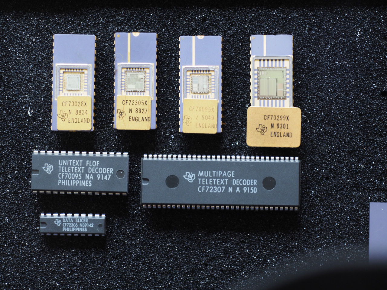
TI made quite a few variations on Unitext, and, as mentioned above, some were specific to single TV manufacturers. It was decided to make 2 types of Unitext which used the same I2C commands, one for Western Europe and one for Eastern Europe so that we could sell into most of the other TV manufacturers. The CF70095 contained the Western European character set and the packet 26 capability, the CF70195 contained the Eastern European character set (data sheet for both). Here is a photograph of all the types of Unitext that I am aware of, with and without lids, small and large packages with the exception of the CF70028 - there's a photo here among Colin Davies's collection. There are three different sizes of process between them, the largest being the CF70064, and the smallest being the later CF70095 (shown in the above photo). Here are photographs of the Unitext CF70095 chip and the CF72301 chip along with the data slicer CF72303 chip (from Colin Davies).
We sold thousands and thousands of Unitext devices to TV manufacturers all over the world, but needless to say, some of these weren't without their problems. To fix a problem that I can't remember much about, I went out to Sharp TV which was in the middle of the jungle in Malaysia. The problem was eventually solved with the help of Colin Davies and others in Bedford. Unusually the teletext was mounted on a sub-chassis, but I've no idea what the rest of the board did. I flew out via Bangkok and returned via KL and Singapore just as I was getting over the jet-lag.
Bustor
In 1993, with management being impressed with the sales of Unitext, we suggested that we develop a device with more features and more pages. This suggestion was accepted but it had been apparent when selling Unitext that we could only sell Unitext and any future devices into TV manufacturers who were prepared to develop their own microprocessors. A lot of the TV manufacturers used the Philips Safari TV controller and this used a different command set for control of the teletext decoders. It was suggested that we generate a chip to convert the codes on the I2C bus directed at other teletext decoders into the codes that ours required.
Trevor was part of the way through the next development when this request was put in, so we stopped work on the decoder part and started concentrating on the bus translator. I was tasked with generating the specification while Trevor started on the known parts of the hardware. We had a TV (made in Poland) for the prototype for Bustor, made by Curtis and which used the Safari interface. We later received another of their excellent TVs in thanks for the work we had done in fitting Eurotext to the chassis (this was the only time this happened, though lots of TVs used for our prototyping in the lab were given to us when we had finished with them). I paid an interesting visit to Curtis in late 1993. I'd never been to Poland before, as this was not all that long after the fall of the Communist regimes. At the time only zloty were allowed as currency (in theory) and there were an awful lot of these to the pound! It was pointed out to me by my hosts in Warsaw that some of the buildings were grey and others painted in Western styles. The grey ones were council owned and the others were privately owned, having all been communist owned not long previous and all grey.
After some weeks we had a working "device" and sent the Orcad drawings to our ASIC (Application Specific Integrated Circuit) department who generated the layout for the device and off it went to the fab. It came back a short time later as a ceramic prototype device which worked (much to our amazement). This device was named "Bustor" and was designated CF70128. A later device was the Bustor 2 (CF70138).
Eurotext (Texas Instruments)
Colin Davies tells me: "I remember working on Ken Ritchie & Jalal to persuade them that an 8 page device was a viable product to attempt at 1um. This was key to getting the big sales and we ended up being designed in at just about every TV manufacturer in Europe and the Far East."
We commenced development of the 8 page device that was to become known as "Eurotext". Trevor started on the micro-code and I started on the design of the parts that I had been responsible for on Unitext (quite a lot of modification was required), but in 1988 he was persuaded that he might like to go to Germany to work on a teletext device there. He accepted this offer and Simon Jones (no relation to Trevor) joined the team to continue work on the microcode (steep learning curve).
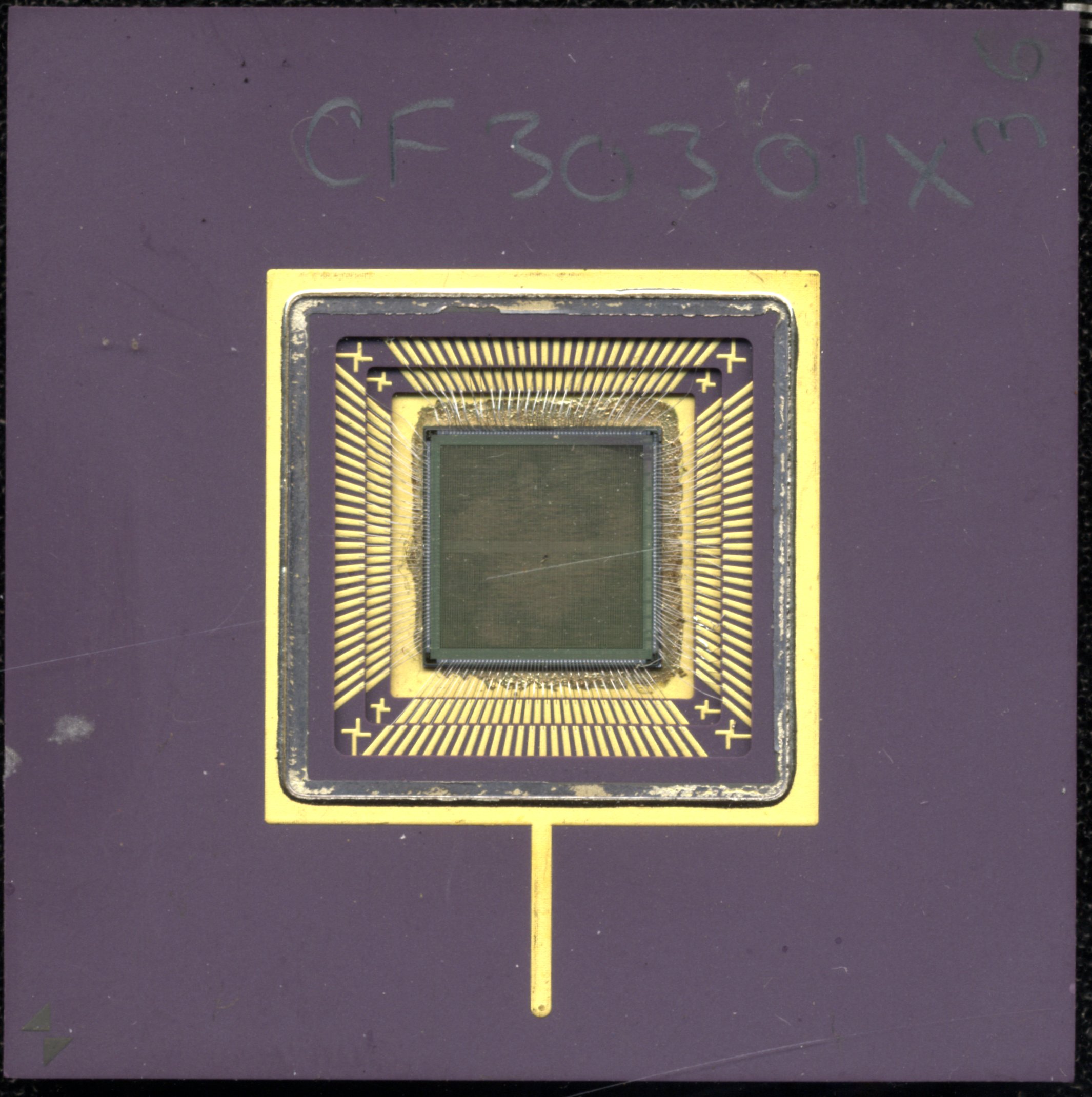
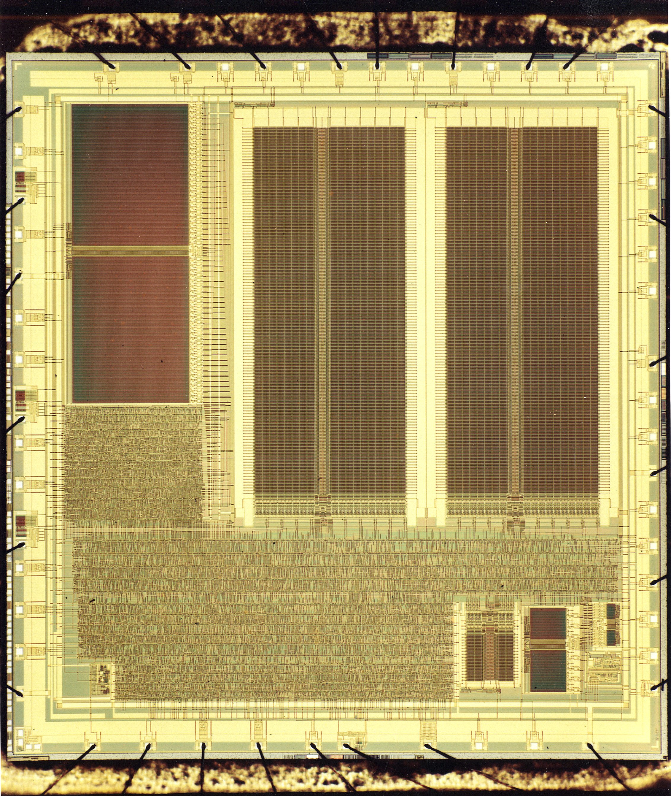
I drew the design for Eurotext on an Amstrad 1614 PC using a very early version of Orcad, all previous designs having been hand drawn. Due to the complexity of the design and Orcad only just having been released I spent lots of time on the phone with their developers. I did the design "bit by bit" as Orcad could only do a relatively small amount of simulation. After Orcad simulation, I forwarded each section to Steve Cooper in the ASIC group who checked each section and did the simulation on his Sun workstation, coming back to me with any recommendations for changes. When we had a full system that would simulate on the Sun workstation, a gate array was generated which contained the whole of the decoder logic but in parts - VDP, front end, Arithmetic Logic Units (ALU) etc., 7 in all. I designed the emulator board to go with these - the largest board I ever designed. I sent the design to Richard Miles asking for a multilayer board with internal earth and power planes and that each of the other connections to the large gate arrays and other components be brought to the surface so that we could either connect to it (for de-bug) or cut it if necessary. Here is an Orcad circuit of the digital part of this board, the analogue section (which used separate power and ground planes) and the edge connectors connections. A prototype of this board came back and I assembled it with a full compliment of devices and to my amazement it worked! We found a couple of problems later but they were easy to fix. 8 more boards were ordered and delivered - all worked except for one that was never tested and I still have it as an unpopulated board (it was used for tracing tracks). The CF30301(scratches are on my scanner glass) gate array functions were determined by where they were situated on the board by the code on 3 of the pins. This turned out to be a good idea as the yield on the devices wasn't 100% due to them being huge and on the leading edge of the technology at the time, so we could select a part of the gate array that worked.
On the Unitext project, one of the things that took a long time was the generation of the character ROMs - these should have been defined in a text file in which there was a ROM address and the byte of data that went there, line by line, the problem being that the characters were defined as 12 by 10 pixels and not 8 by 10. Eventually we managed to arrange that the definition would use the ROM address followed by 12 bits instead of 8 (in hex). However it was more than somewhat tedious to do this and the opportunity for errors was high and so I set about looking for a better, automatic, way of doing this. We also needed to generate a graphic showing each character for the data sheets for the devices, particularly as Eurotext was going to use many more characters. I decided that the way to generate the data for the character ROM required by the ASIC group was to define the characters in a text file where each character was defined with 10 rows of dots and X's (a .xmp file), a dot being background colour and an X being foreground colour. Writing the software to do the conversion from this format to the ROM definition was then quite straightforward and I hit on the solution to the data sheet images quite by accident. I was looking through the Orcad files trying to find out how to do something in the component library definition when I came across files with component names that appeared to have no use. However on investigation I discovered that they were the original text files used to define the components in the various libraries. I had a further look round to see if there was software to convert these into component definitions and found it. Clearly this was the original way of defining the component shapes before the advent of the graphic interface and I could use this! I wrote software to convert my ".xmp" file to a component definition in a text file and then ran the Orcad conversion software to generate the component shapes and then used Orcad schematic capture to layout pages of characters (components) as required for the data sheet(s). This may seem a convoluted way of doing things, but believe me it was days quicker than the old method and also error proof so long as the basic .xmp file was correct. I have some of these files on this site: Latin only, Latin, Cyrillic, Arabic and Greek, Hebrew, Arabic and Vietnamese. The character images these produced are given in the data sheets below.
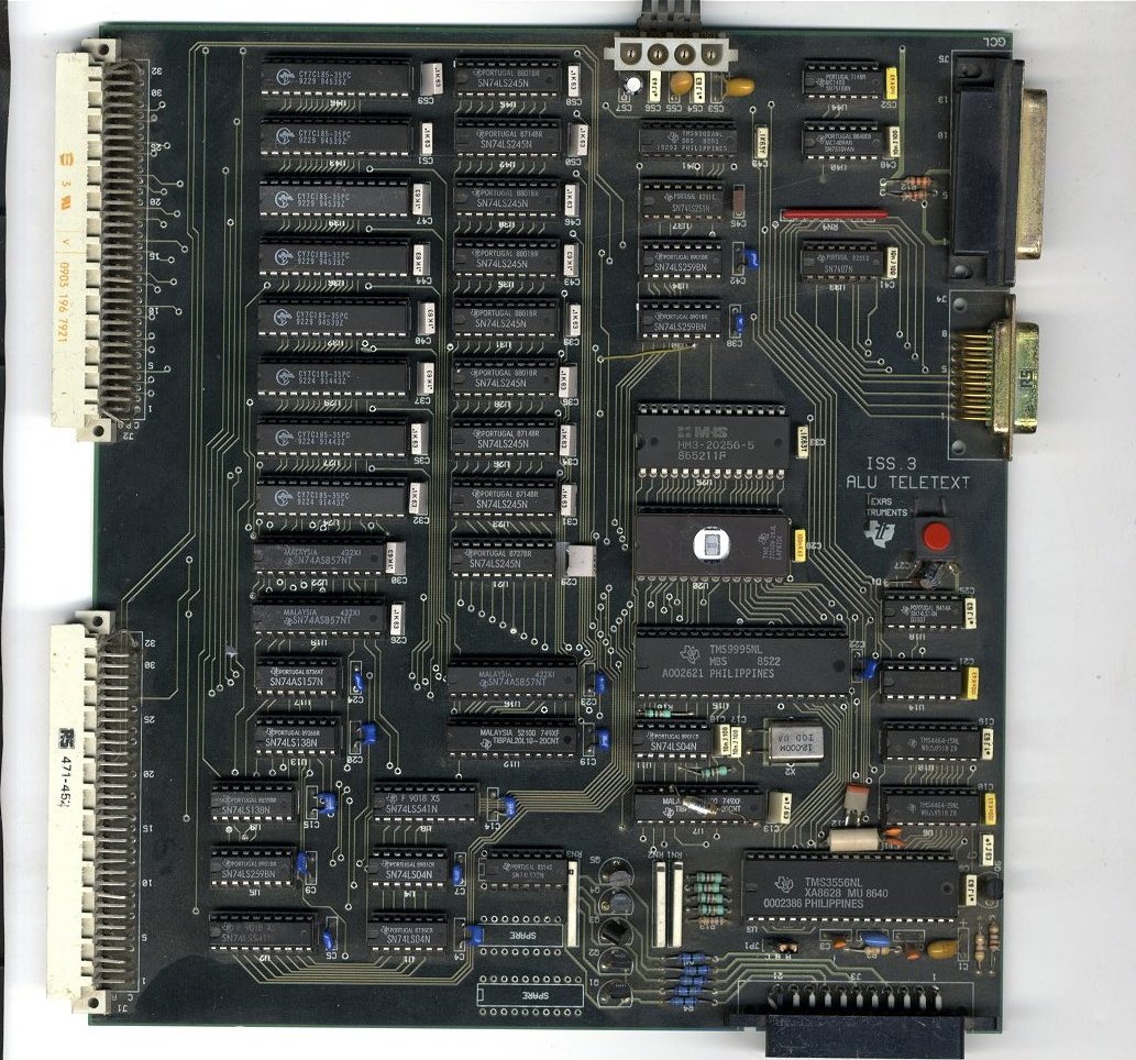
The ALU for Eurotext needed to be capable of addressing the 8 pages of display RAM. When access to the RAM was simulated it was found that there was a propagation delay problem which turned out to be due to the ripple carry in the ALU. Robert Nokes (ASIC group) found that the design for the ALU ripple carry left something to be desired and spent quite some time reducing propagation delays until he eventually got this to pass the simulation. At this point all seemed well and the design was sent off for mask generation and in due course we received a device back from the fab - this was known as the CF70299 and only just fitted into a (special) 28pin ceramic package. The device was functional (lots of happy people!), but clearly we weren't going to be able to produce devices in large numbers at a competitive price, however the fab was about to change from the 2 micron to the 1.5 micron technology. Once we had thoroughly checked out the CF70299 and made any changes we thought necessary, we asked for the changed device in 1.5 micron technology. This fitted into a standard package and was known as the CF70200 Eurotext.
The CF70200 device was capable of using the German Table Of Pages (TOP) system (as well as the Full Level One Features (FLOF) that was more generally used). Having more than 1 page of storage made the FLOF system really nice to use, as the pages "behind" the coloured buttons on the handset could be captured as soon as they were available on the transmission once the initial page had been captured.
In the 1994/95 period, Simon Jones left TI and the Multipage project (see below) came to an end which resulted in Trevor Jones coming back into the Eurotext project (in Germany) and doing any updates required on the microcode. Trevor gave me a list of his work on Eurotext and I have added these below:
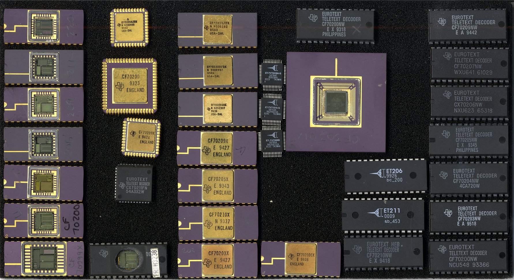
TI made several variants of the Eurotext devices. I still have samples of them shown in this photograph along with the later Europe Technologies devices.
* VPS (Video Programming System) with a later data slicer, the CF72416 (data sheet) than that used for Unitext could receive and decode the Video Programming System signal that was transmitted to control home video recorders (regardless of whether or not teletext was being used at the time).
** WSS (Wide Screen Switching) with yet another data slicer, the CF72417 (data sheet) could decode the Wide Screen Switching signal and output the result so as to control the width of the display on the TV (regardless of whether or not teletext was being used at the time).
We made lots of these and changed technologies as the yields got better and better, selling millions world wide.
You will notice that at the bottom of the above list of devices is a Greek device. One day I got a phone call from Philips (our main teletext competitor) asking if we would be interested in doing a Greek language decoder for them in time for the Olympic games in Greece. I asked which department he was from and the answer was the TV design. Very strange I thought, but I took his phone number and said I would ring him back. I discussed this with Colin Davies and we decided that we needed more details before we went any further. I rang back and discussed the matter with them. When I asked why they had come to us and not Philips Teletext designers, the answer was that they had asked but they didn't think that they would be able to do it as the Latin languages were required too. We had a meeting at TI and decided that we would go ahead with this - it was really a case of simply switching between the Latin G0 alphabet and the Greek Primary alphabet (96 characters) and so was quite simple and took us 3 weeks to implement. We sent what we hoped was a fully working emulator board to Eindhoven and they were over the moon with it. TI produced some sample ICs for their designers and some time later Colin Davies and I were invited to Eindhoven to see the working prototype TV. I was very surprised to see that my emulator board had pride of place in their display cabinet in reception!
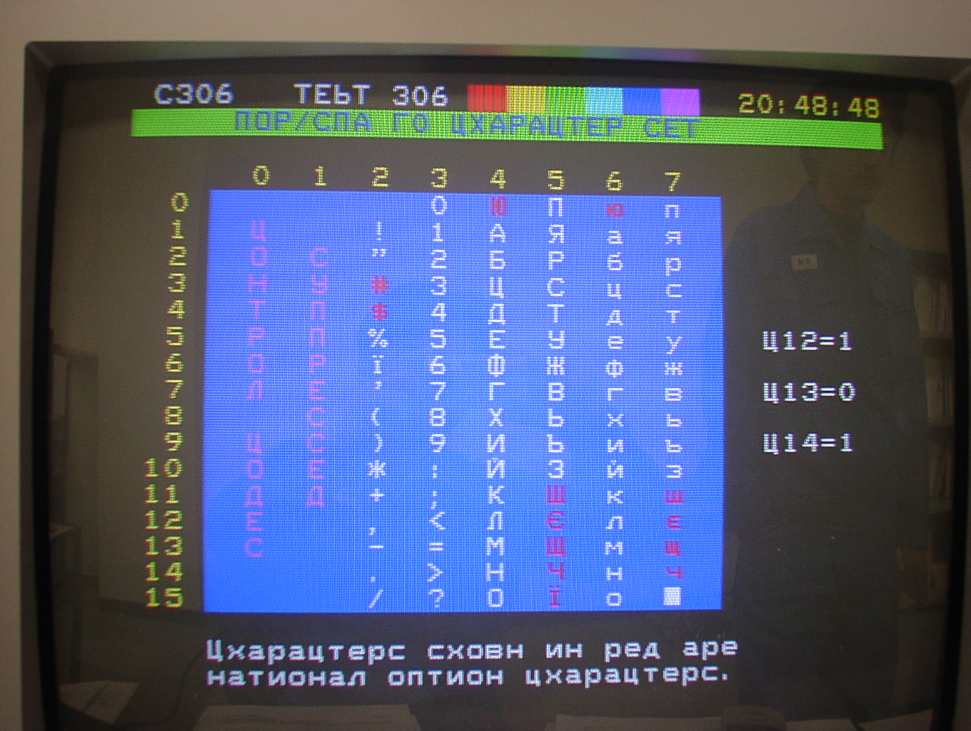
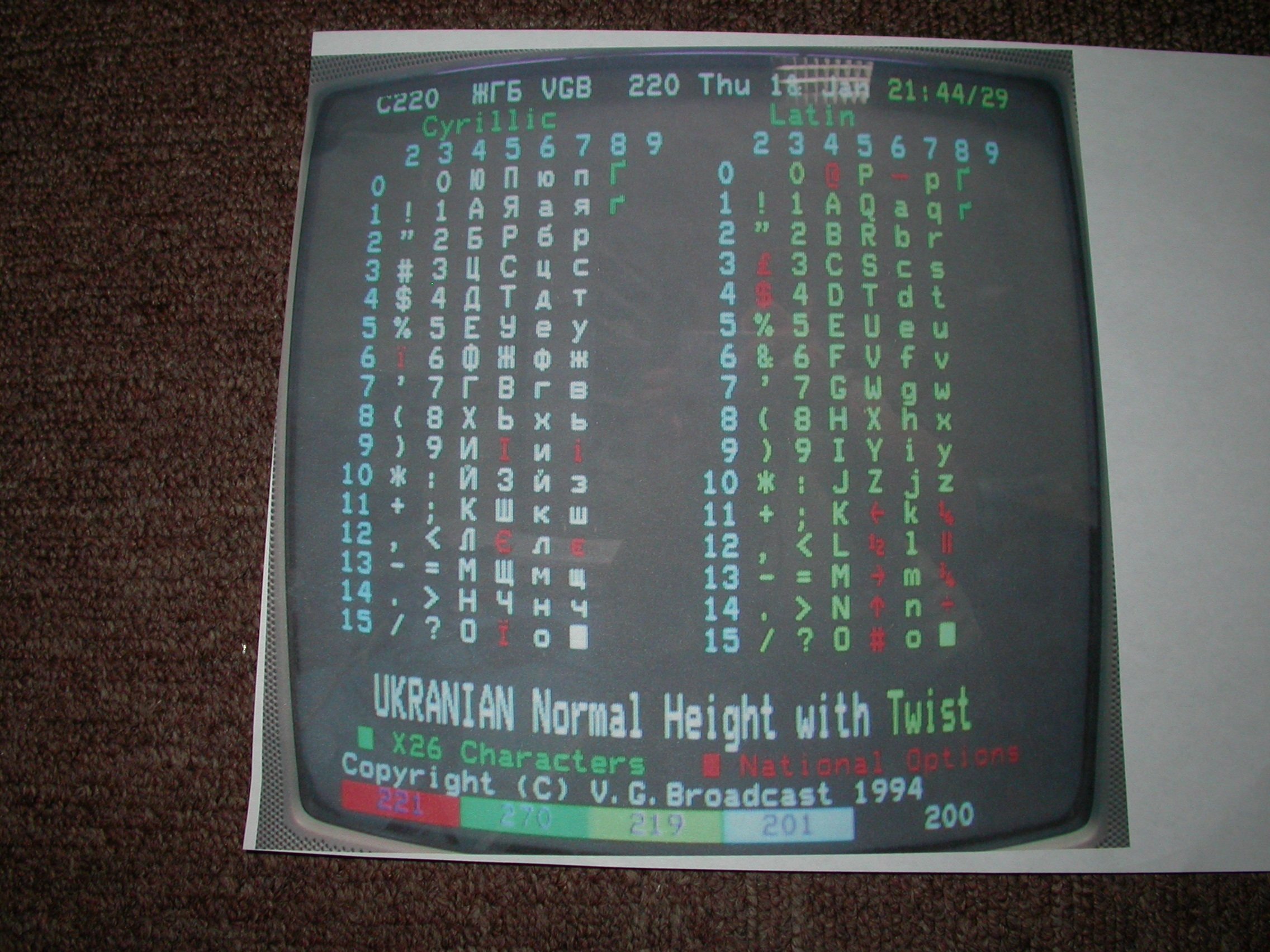
Character sets (again): As TI was the first company to generate a Greek teletext device it befell to me in conjunction with our Greek contact to define the Greek primary and secondary character sets and these are the characters that you see in the later ETSI Enhanced Teletext Specification (para 15.6). A similar situation arose with the Russian and Ukranian characters sets we used in the later Eurotexts. In conjunction with Alexy, our Russian contact, I developed the Russian character set and defined which characters would change for national options between the Russian and Ukranian. These too later appeared in the ETSI spec. although I was never asked for them directly. Also in the later spec. was the ability to switch between alphabets on the same display row. This used the "twist" character (actually the ASCII escape character). Here is a photograph of this feature from the VG generator manual as displayed by a CF70212 showing the "twist" feature and the two different sets of "national options" (in red). Note that the two packet 26 characters in column 8 come out the same in both alphabets. Later came Vietnamese, but that's another story!
In order to be able to demonstrate Eurotext, we totally redesigned the evaluation board such that the PC/TV interface board had the teletext decoder as a vertical daughter board. This once again used the SCART connection to the TV and a parallel port connection to the PC. Adrian Dowle modified his software so that it could deal with Eurotext instead of Unitext. Here is a photograph of the two small boards. Adrian also had a hand in generating the Software Application Guide which provided customers with all they needed to know in order to drive the Eurotext devices with the TV microcomputers.
In 1995 TI decided to close the Bedford plant and sold off the "power" fab which eventually became owned by Bourns. Some of the staff moved to Northampton (me included), but we stopped analogue teletext development and I moved on to digital TV and the associated teletext. In 1996, Borland brought out their Borland C++ compiler and I started using that for my software - a much easier to use Integrated Development Environment (IDE). This ran under Windows 95 and I still use under Windows 10 with a couple of simple work-arounds. In 1997 TI decided to get out of analogue teletext and I had the job of archiving all of the data and paper work involved in this. In 1998 on the day of our 30th wedding anniversary I was made redundant (actually "early retirement"). 3 days later I received a phone call from Rob Mathews in France, then working for a company called Europe Technologies who were looking for "a person who knew about teletext" as they had bought the rights to some of TI's teletext devices and teletext patents. As there didn't seem to be many openings for a teletext designer at the time, I negotiated a deal with them and worked for them for the following 7 years.
Multipage
As I previously mentioned, Trevor Jones moved to Germany to work on a teletext device. This device became known as "Multipage" designated CF72307 (User guide) and the later CF72407 (User guide) . It was based on the code and work that I'd done on the project for Instant Text - the number of pages it could store was limited only by the amount of RAM it was given. The techniques used on Multipage were patented and the names on the patent are Trevor Jones, Helmut Fink and myself. In the 1994/95 period, Simon Jones left TI and the Multipage project came to an end which resulted in Trevor Jones coming back into the Eurotext project (in Germany) and doing any updates required on the microcode.
Eurotext (Europe Technologies)
Europe Technologies (ET) was based in Sophia Antipolis, France, which is to the north west of Antibes and north east of Cannes. After my many trips into Nice airport for TI, I now started many trips into the same airport for ET and had a total of around 120 trips from the UK into the airport. If you've been into Nice airport, you'll know that the first time is quite frightening as the runways are parallel to the coast but out in the sea and so as you come into land you are over water until about 5 seconds before you touch down - I've known people scream in fear as there is no warning of this!
The deal I negotiated with ET was that I work from home in the UK and travel out to France only when they thought it was necessary. We drove down to ET by car to do all the relevant paper work and had a week's holiday at the same time. We stayed with Rob Mathews and his wife Gloria who we already knew from our 10 week stay in Cannes sur Mer. When I got to ET I found that Marc Goddard was also working for them - I had worked with him previously on the TMS3551 project at TI France.
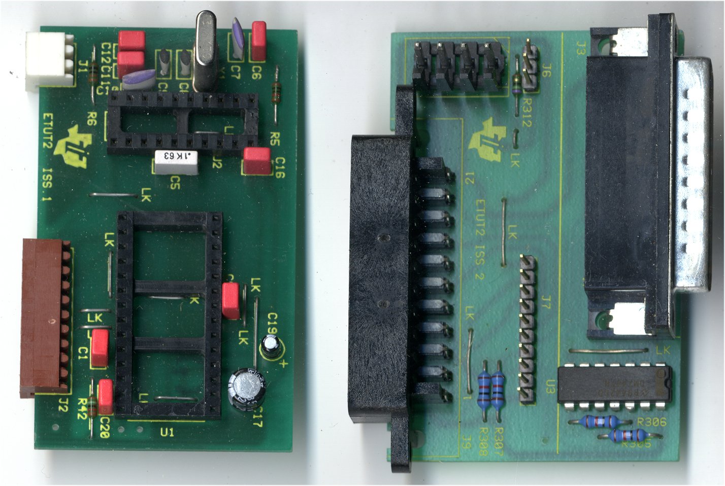
ET had bought the data for the devices CF70206 and CF70211 from TI. Unfortunately the description for these was in TI's High level Description Language (HDL), but ET needed this in Verilog. By the time I arrived on the scene they had generated what they thought was the equivalent of TI's HDL description for the CF70206 but had no means of verifying it, so my first job was to do this. Comparing the two gate by gate in text descriptions is mind boggling! I decided to do this by software (with my nice Borland compiler), and although it took me two weeks, found several errors which were then corrected - another run of the software claimed that the two descriptions were the equivalent of each other and so they went to a fab and got devices made - they came back fully functional. ET management were even more amazed than those of us who had worked on this (Christine Dubois, Alexandre Mengeaud, Pascal Jullien and (the late) Knut Anderson to name some of them). After this we did the same for the CF70211 and had the same success. The Europe Technologies devices were designated ET206 and ET211.
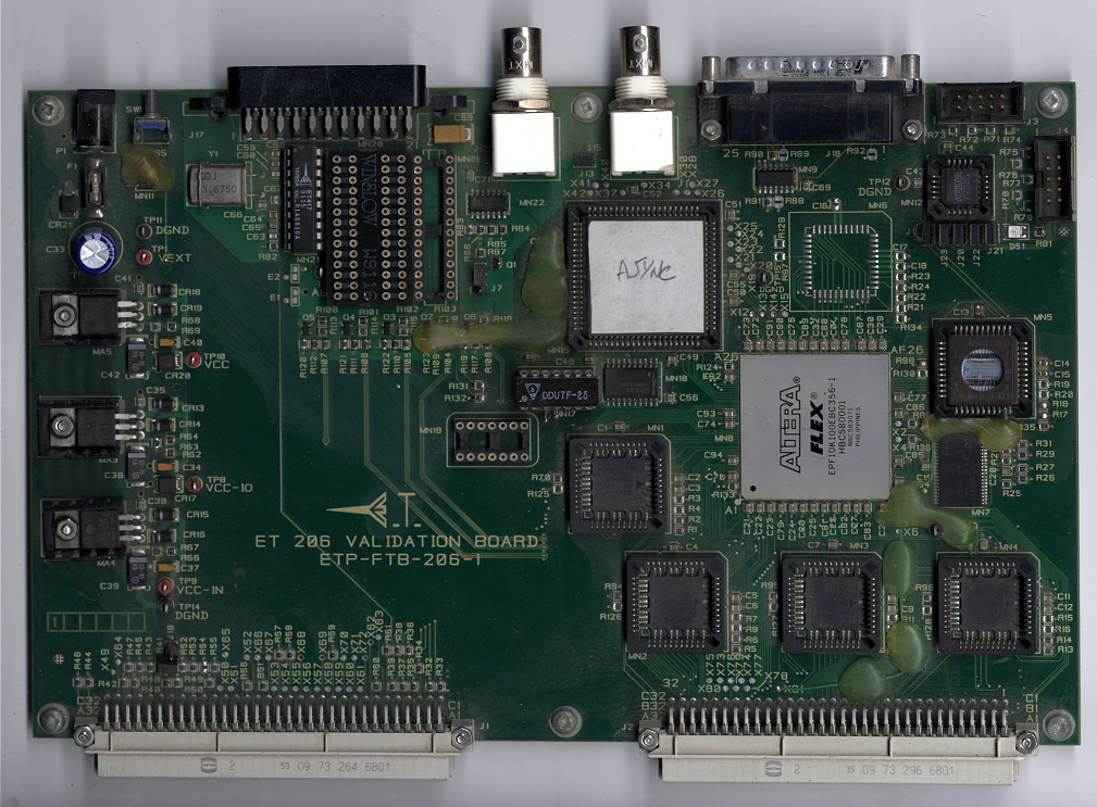
Following this, ET wanted to do further development and they had my Emulator board with the gate arrays and my Control board. They got these up and running and I obtained from TI the VG page generator, which of course was of no further use to TI. In order to proceed any further with my emulator board, it would require making new gate arrays (different gate arrays were of course required for each version of Eurotext due to the logic changing). Alex Mengeaud set about designing an equivalent board but using a single Field Programmable Gate Array instead of the 7 fixed gate arrays we had previously used. Once we had his board up and running we could change the decoder logic at will by downloading data into the FPGA either from a PC or an EPROM. This system still used my control board and so we didn't need to make serious changes to the software to drive Alex's FPGA board. We started with the CF70206 code as a test for this and managed to get it up and running after one or two minor problems. ET wanted to add a digital data slicer to make the decoder system a single chip, but they had no one with any experience in this field and so at my recommendation, they asked Bob Camp (ex contractor to TI) if he would like the job and he accepted.
Data Slicers
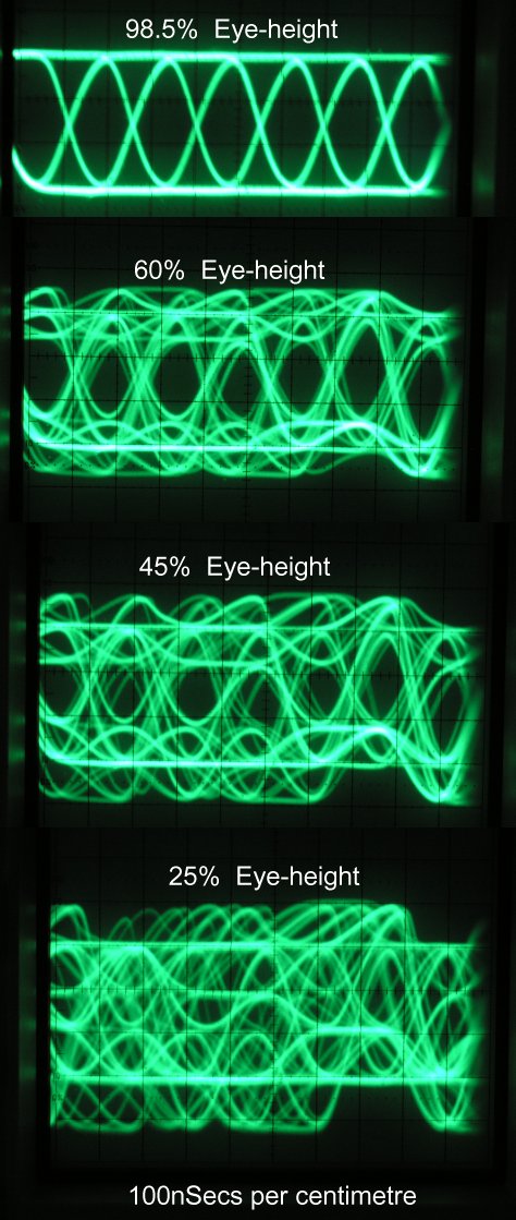
I've not previously mentioned anything about slicing data out of the TV video, so here goes. Teletext data is transmitted on lines in the Vertical Blanking Interval (VBI). If it was transmitted as square waves then the bandwidth of the signal would be huge and so it's transmitted in a "non return to zero" format - more or less a sine wave or at least sine wave edges. If you look at the data on an oscilloscope and trigger the scope using a synchronised clock, you will get overlapping 0's and 1's in sine wave format. So long as the DC level remains constant, the data slicer can pick a voltage at which to slice through the middle of this, this giving a 0 when the data is below that level and a 1 when it's above. The problems arise in that the DC level tends to move during the line of data and there are distortions to cope with (such as TV transmission reflections). Changing DC levels mean that the slicer tends to be biased one way or the other and a reflection added to this can mean that the sliced data is incorrect as the 1 level has sunk below what the slicer thinks is a 1 or vice versa. Looking at the waveform on the 'scope shows what looks like an eye, and varying the distortion changes the shape of the eye - increasing the distortion causes the eye to become more and more closed. Clearly if the eye is closed, then it's impossible to recover any good data from the input. If you take the eye being fully open as 100% and fully closed as 0%, then it's possible with a signal generator to introduce known amounts of distortion and so know what the "eye height" is as a percentage. Data slicer capability can thus be measured by increasing the distortion on a given teletext signal until errors are seen to occur on the displayed page - the point at which this occurs being the minimum eye height capability of the data slicer. With the analogue data slicers used on Unitext and Eurotext we usually got down to around 12% to 15% eye height. The data slicers used on XM11 and XM12 didn't normally get better than 15%, and the Wireless World slicer was around 25%. The need for a high performance slicer was really in locations which used repeaters for the TV signal with no teletext reformatting done. This was particularly severe in the Malaysian valleys where the signal bounced off the side of the valleys to the repeater and was then re-transmitted complete with reflections embedded and usually with part of the clock run-in signal missing from the front of the waveform (this was used to synchronise the teletext bit clock to the data). Eye heights in this area were often down to 10-12%. Here is a photograph of the Data Slicers I worked with, with and without lids. Data sheets: CF72416, CF72417.
I got out my VG Teletext generator, plugged it in (after 25 years neglect) switched on and the lights came on, there was sync, data etc on the front test sockets, but no video on the output at the back. While looking for what might be the problem with this, smoke poured out the back. The mains filter capacitors had decided they didn't like mains any more - the smell was incredible! The generator seems happy with burnt out main filters so I carried on. 60+ screws later I got into the output board and found that one of the relays just before the output driver circuit was open circuit on one of its contacts. The reed relay was made by Pickering Electronics Ltd of Clacton, and so, ever the optimist, I looked them up on the web, contacted them and they happily supplied a relay of exactly the same type - I was amazed! (thanks Sam). As a result of getting the generator to work with the new relay I was able to take photographs of eye-heights. The 25% one isn't very good as the 'scope triggering got very confused with this, but you should get the general idea of the problems with low eye heights.
What we hoped Bob Camp would achieve was something better than 12%. What we got was an amazing 8% at worst and sometimes 5% - it could also produce a synchronised clock with only 4 of the 8 cycles of clock run-in. We went ahead and designed a device similar to the CF70206 that included Bob's data slicer, the TVT008. When it came back it performed as predicted and so we now had a single chip decoder including the data slicer. This device, the TVT008, came in a 48pin plastic quad flat pack - the part, excluding the pins, was smaller than the CF70299 silicon! We couldn't use Alex's equivalent of my emulator board for this device as quite a few things changed due to the digital data slicer and so Alex designed a new board and I used this to write the microcode with.
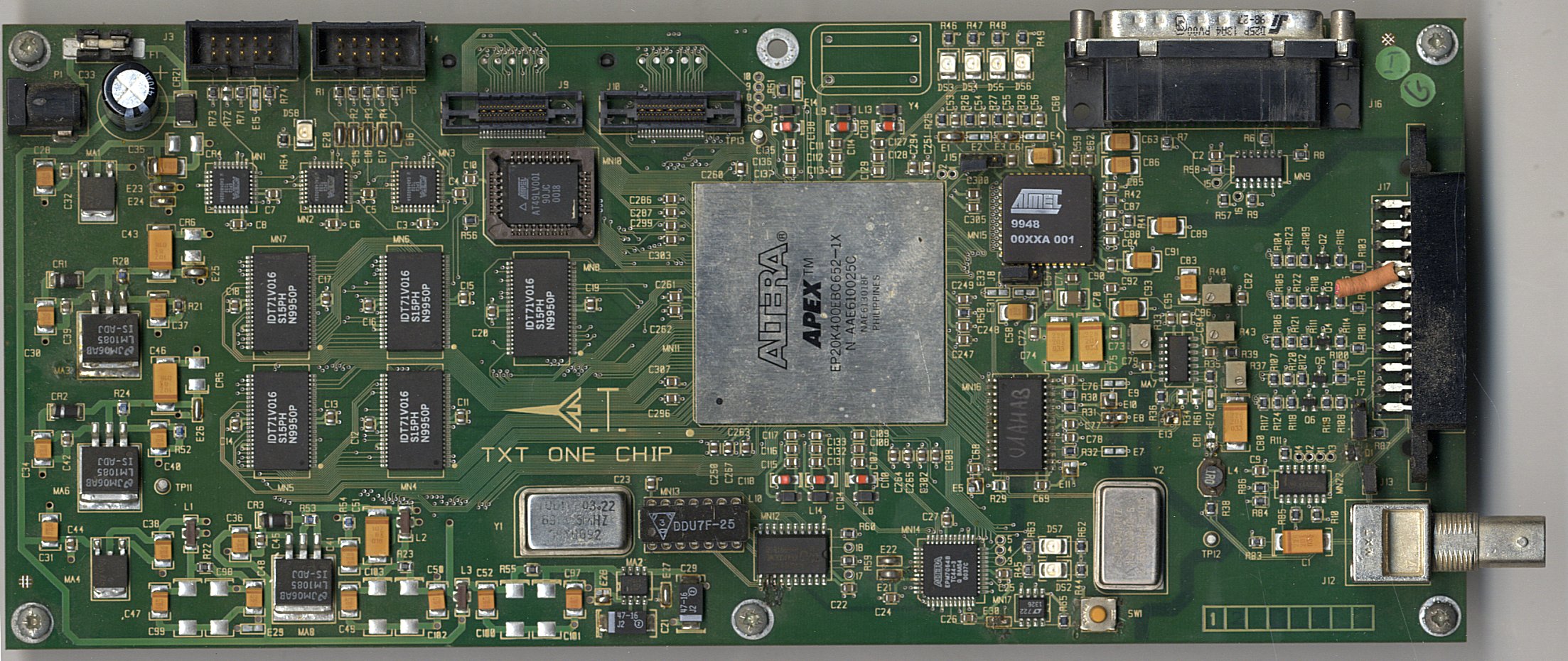
After this we produced a 10 page device (TVT310) - this involved a change in the ALU to 12 bits (to access 10k of RAM) and changes in the micro-code to deal with this. All the changes in the design became my responsibility including the microcode - fortunately I didn't have to do the simulation etc. as Christine Dubois did this. Here is a photograph of the 10page TVT310 installed on a TV chassis. For anyone interested, the top level circuits for the character ROMs are here: 8 page, 10 page.
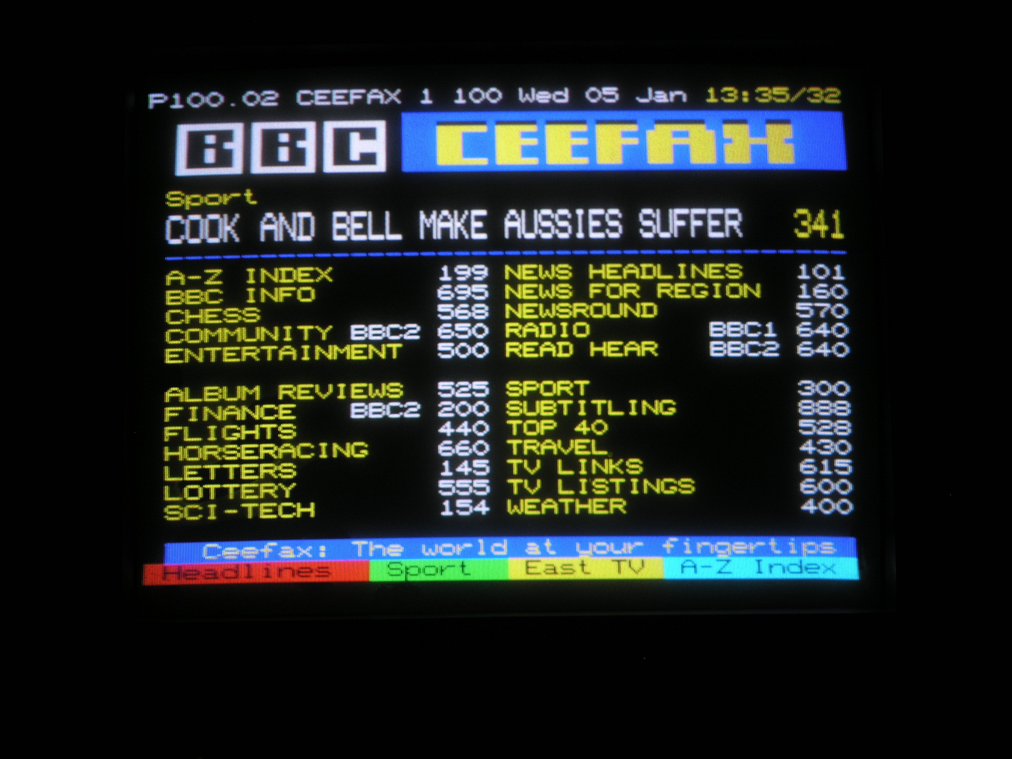
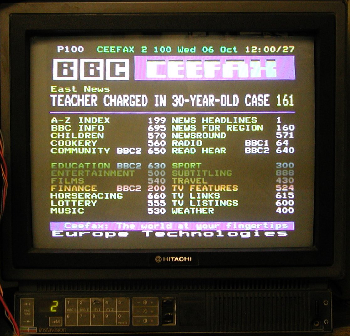
While working with Europe Technologies I would spend several weeks working well over 12 hours a day at home doing the microcode and hardware design, then several weeks going between France and the UK. When we were happy with the device, then it would go off to the fab and usually I would get 3 or 4 weeks "off" until the device came back for checking. Here is a photograph of one of my test pages (copy of a Ceefax page with a special bottom row), shown on the TV, which as mentioned above, was given to me by Channel 4. Among other things that were introduced with the later teletext specifications were double size and double width, and these were implemented on the Europe Technologies TVT decoders - there's a photograph of this feature here - the page actually shows "flash" too, but it happens to be in the off state when I took the photograph.
Decoder for Vietnam
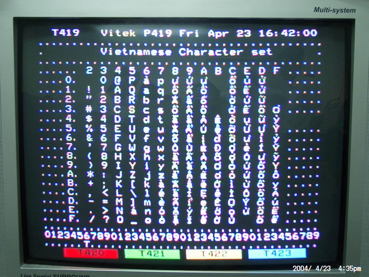
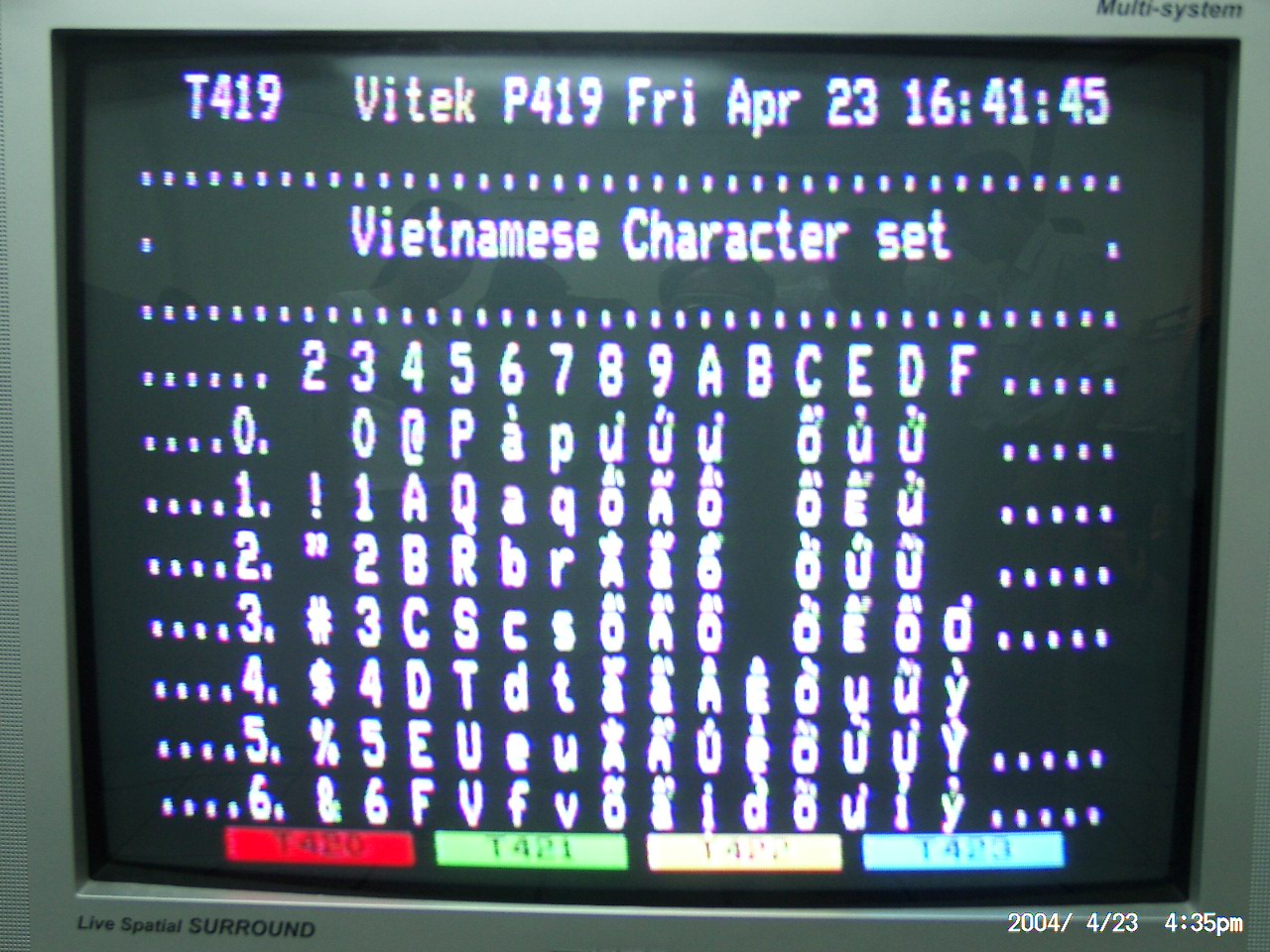
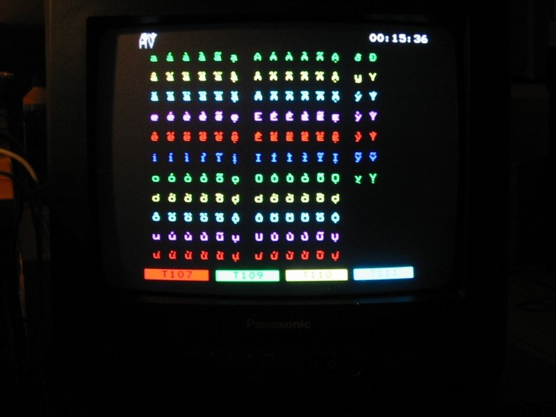
In 2003, ET got a request from Vietnam for a decoder. Talking to Cebra (the maker of the PCI teletext transmitter for Vietnam) apparently the competition had been working on this for well over a year and had given up. The problem was that the number of characters was huge, and used massive numbers of packets 26 to get the characters which in some cases prevented the TV processor from completing the page before having to deal with the next incoming page. If asked what character set was required for this, I would have had a guess at Thai or Chinese - in fact it's a Latin alphabet with up to 3 accents on some characters. It is possible using lots of RAM to assemble a character and place the accents on it using software. However, there are problems with this as in some cases it is necessary to change the shape of the character in order to add the accents in a 12 by 10 matrix - in any case there was no way we were going to be able to do this in real time and it would use more RAM than we could accommodate. I asked how many extra accented variants were required and the answer was between 136 and 143. After working out just how many we could deal with, the answer was 128. This meant that we needed to lose sufficient Vietnamese characters to get us down to that figure. After much discussion we got down to 128 much to my surprise (and to Cebra's). To accommodate this, it meant either having a Vietnam only device, or a device such as the TVT310 with Vietnamese added - we chose the latter. To do this meant switching out all the European alphabets and switching in the Latin set for Vietnam, plus the Vietnamese 128 characters. We'd never had to do this before and it caused a few headaches, which I eventually fixed by designing a different way to access the character ROM. In conjunction with Cebra, we decided which code should access which character and therefore its position in the ROM, which now had a 9 bit address, one from the European/Vietnamese switch and the other 8 from the display RAM. This display was composed of lots of characters with accents and so had lots of packet 26 accessed characters - all in the upper part of the ROM. Cebra sent me a PCI generator set up with Vietnamese and within 3 weeks I had a working Vietnamese decoder using Alex's emulator board system.
I have some photographs of the displays for Vietnamese, some of them not very good:
I have photographs of most of the ET devices, these are shown with the TI devices.
After the TVT410 went into production, we started looking at using an ARM processor instead of the RISC processor, but it soon became obvious that analogue TV was on the way out and digital was the up and coming thing. I retired (sort of) at the end of 2006 and the rest of the teletext team started on other things.
Teletext Specifications
Teletext pages
As I mentioned above, I have a heap of Sky One pages from 1997 in text format. I have re-generated these for display here.
My thanks to:
Have I mentioned you (or not mentioned you) and you have something to add, please drop me a line (see below for link).
After I set up this page, Laurence Cook (of the now defunct Citifax) kindly sent me his MRG Systems SB56 Teletext Inserter Technical User Manual, thanks Laurence.
Colin Hinson.
If you're bored, see also my Radar Pages, Blunham pages and Genuki pages and if you're really, really bored in the period of lockdown you might try "Blue balls" or "Blue balls 2" (try following one of the balls!).
If you have any comments, complaints, suggestions, requests etc, please drop me a line via my Genuki email page.
Page last updated 22nd January 2021 by Colin Hinson.